


Push Button Configuration
Use the push button to configure the sensor. Click the push button according to Push Button Input Flowchart. After a configuration
has been selected the sensor flashes both the green and amber LED to show which configuration was selected followed by a rapid
flashing of both the green and amber LED in unison to show acknowledgement and acceptance of the configuration.
Unlock push buttons (flashing Green and Amber 1X followed by acceptance flash) default
Lock push buttons (flashing Green and Amber 2X followed by acceptance flash)
Enable Auto compensation (flashing Green and Amber 3X followed by acceptance flash)
Disable Auto compensation (flashing Green and Amber 4X followed by acceptance flash) default
Enable 30 ms Off Delay (flashing Green and Amber 5X followed by acceptance flash)
Disable 30 ms Off Delay (flashing Green and Amber 6X followed by acceptance flash) default
Click 2X
Basic Configuration (alternating flashing Green and Amber LEDs at 1Hz)
Advanced Configuration (simultaneous flashing both Green and Amber LEDs at 1Hz)
Press and hold push button > 2 sec.
Hold is > 2 sec. and < 4 sec.
Click is > 40 ms and < 800 ms
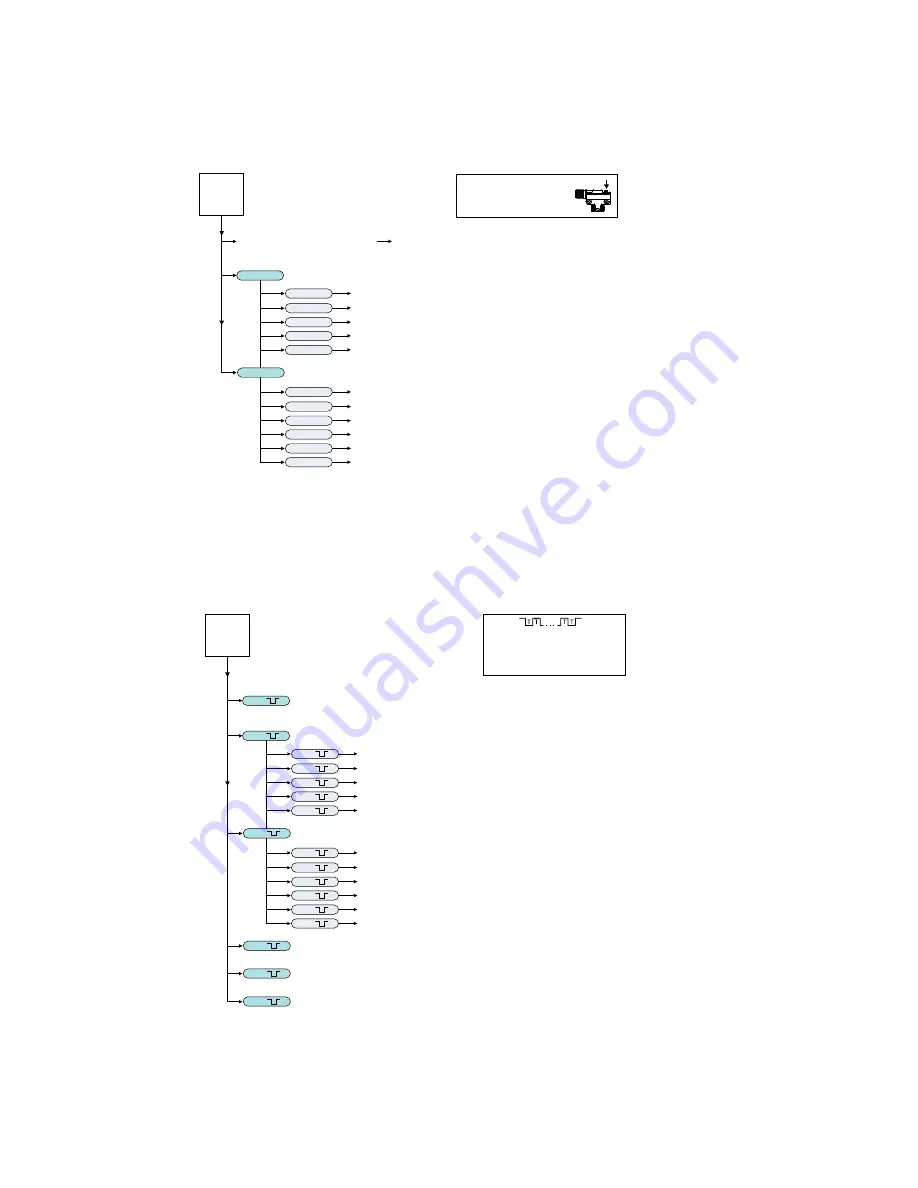
User Interface Push Button
(configuration using push button)
Initiate LIGHT/DARK SET
Click 2X
Click 1X
Set output to Light Operate (flashing Green and Amber 1X followed by acceptance flash)
Set output to Dark Operate (flashing Green and Amber 2X followed by acceptance flash) default
Click 4X
Click 3X
Set offset to 8% offest (flashing Green and Amber 3X followed by acceptance flash)
Set offset to 16% offest (flashing Green and Amber 4X followed by acceptance flash) default
Sensor
Push
Button
Click 5X
Set offset to 32% offest (flashing Green and Amber 5X followed by acceptance flash)
Click 3x
Click 2X
Click 1X
Click 4X
Click 3X
Click 5X
Click 6X
Figure 1. Push Button Input Flowchart
Remote Input Configuration
Enabling the remote input wire is done using IO-Link. Use the remote input function to configure the sensor remotely. Connect the
white wire of the sensor as shown in the wiring diagram. Pulse the remote line according to the Remote Input Flowchart. After a
configuration has been selected, both the green and amber LEDs will flash to show which configuration was selected, followed by
a rapid flashing of both the green and amber LED in unison to show acknowledgement and acceptance of the configuration.
2x
1x
Unlock push buttons (flashing Green and Amber 1X followed by acceptance flash) default
Lock push buttons (flashing Green and Amber 2X followed by acceptance flash)
4x
3x
Enable Auto compensation (flashing Green and Amber 3X followed by acceptance flash)
Disable Auto compensation (flashing Green and Amber 4X followed by acceptance flash) default
5x
Enable 30 ms Off Delay (flashing Green and Amber 5X followed by acceptance flash)
6x
Disable 30 ms Off Delay (flashing Green and Amber 6X followed by acceptance flash) default
1x
2x
Basic Configuration (alternating flashing Green and Amber LEDs at 1Hz)
Advanced Configuration (simultaneous flashing both Green and Amber LEDs at 1Hz)
Initiate LIGHT/DARK SET
40 ms < T < 800 ms
Timing between Pulse groups > 1 second
Pulse Timing (T)
(white wire is input wire)
2x
1x
Set output to Light Operate (flashing Green and Amber 1X followed by acceptance flash)
Set output to Dark Operate (flashing Green and Amber 2X followed by acceptance flash) default
4x
3x
Set offset to 8% offset (flashing Green and Amber 3X followed by acceptance flash)
Set offset to 16% offset (flashing Green and Amber 4X followed by acceptance flash) default
3x
Toggle Teach Button Lock/Unlock (flashing both Green and Amber LEDs 4X followed by acceptance flash)
4x
Force Sensor to Maximum Gain Condition (DARK SET) Without LED Brightness
Change (flashing both Green and Amber LEDs 6X followed by acceptance flash)
5x
Reset to Factory Defaults (flashing both Green and Amber LEDs 8X followed by acceptance flash)
8x
Remote
Input
Wire
5x
Set offset to 32% offset (flashing Green and Amber 5X followed by acceptance flash)
(configuration using remote input wire)
Figure 2. Remote Input Flowchart
WORLD-BEAM QS18E Clear Object Detection
P/N 194469 Rev. C
www.bannerengineering.com - Tel: +1-763-544-3164
3


