


25. Demonstrate the reaction of the scanner software as well as the scanner display as you block the two zones. The Demo Kit
box should have the S22 light for the Warning Zone (white wire) turn on when the zone is clear and turn off when the zone
is blocked. The T8 light (OSSD) is green when the Safety Zone is clear and red when the Safety Zone is blocked.
Discussion Topics:
Application examples using up to the full 275 degree zone protection such as:
1. Guarding around all four sides of a stationary machine with openings that expose to hazards. Using two scanners mounted
on opposing corners may be cost effective compared to safety mats.
2. Protecting personnel against a simple moving AGV or mobile apparatus moving back and forth on a rail would also be a
great application for two SX5-B scanners located on two corners of the object.
The SX5-B safety scanner does not have available external device monitoring (EDM). The safety outputs (OSSD1 and OSSD2) will
need to be connected to a safety-rated module or controller that has EDM monitoring (if necessary), such as Banner's UM-FA-FA
module or the SC26/XS26 controllers.
When a
configuration
includes a Warning Zone, you can select one or two zones with assigned outputs for each. This may be
needed for an application that uses each warning output for separate external controls.
Demo Kit Example
Configuration
#2 -- Muting Inputs
The SX5 is able to assign muting inputs as well as supply an output to indicate the muting status is active. This Demonstration
Configuration
shows the scanner's ability to perform these functions.
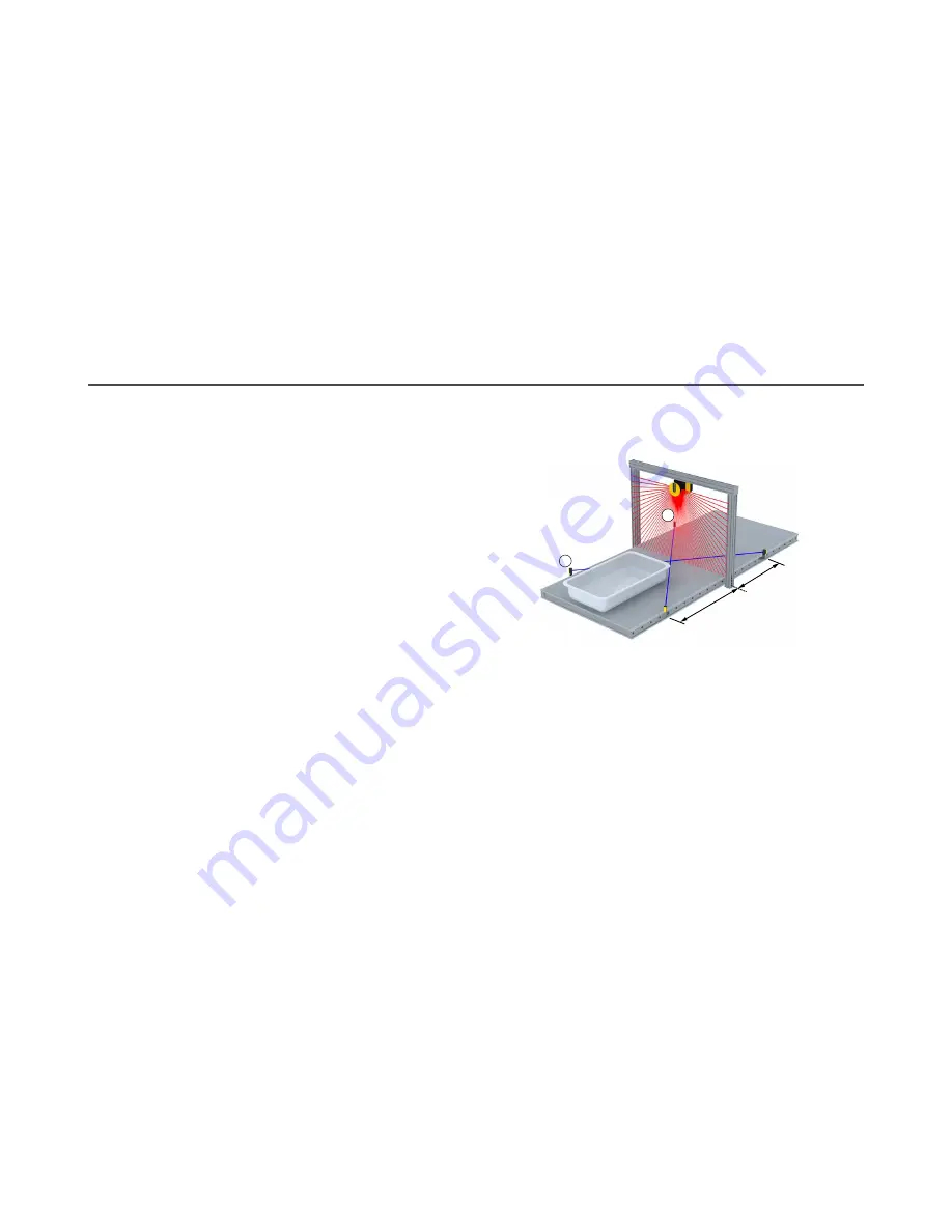
As shown, the SX5-B can be mounted and
configured
to allow
the tray to turn on the M1 and M2 mute sensors, mounted in an
X pattern within the Safety Zone.
The muted state continues operation as the tray moves past the
scanner until the tray clears the monitored X pattern.
M1
M2
D
D
1. In the
configuration
software, go to the
Configuration
> Zone Set screen and change the following parameters.
•
ZoneSetNo: 1
2. Go to the
Configuration
> Outputs screen and
define
the following parameters.
•
Muting: Enabled
•
Muting Lamp: 1
•
Output Signals: Assign PIN 4 (yellow) to Muting Lamp 1.
3. Go to the
Configuration
> Inputs screen and
define
the following parameters.
•
Restart Mode: Automatic
•
Muting Type: Bidirectional (travels in both directions through the Safety Zone)
•
Max Muting Activation Delay: 4 seconds (sets the maximum delay allowed between the activation of M1 and M2)
•
Timeout: 10 seconds
•
Override: Disabled
•
Input Signals: Assign the remaining two pins to Muting 1 1 and Muting 1 2.
4. Go to the
Configuration
> Zones screen.
5. Right-click your mouse at any location on the
configuration
grid to access information about the existing Safety Zone
shape. As you move the mouse to the left, the software shows you where you can click to delete to remove the Safety
Zone shape.
For a demonstration choice, on the left panel click to highlight Safety. On the right, select the (X,Y) tool (or you can use
another tool to create your shape).
SX5 Safety Scanner Demo Kit Setup Instructions
P/N 209666 Rev. A
www.bannerengineering.com - Tel: + 1 888 373 6767
5


