background image

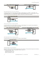
Discrete Input Wiring for PNP Sensors

Discrete Input Wiring for NPN Sensors

Discrete IN

PWR

10-30V dc

Discrete IN

GND

dc common

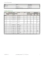
Wiring Diagrams for Discrete Outputs

Connecting dc power to the communication pins will cause permanent damage. For the DX8x...C models, PWR in the

wiring diagram refers to V+ on the wiring board and GND in the wiring diagram refers to V- on the wiring board. To power

the sensor using the switch power output (SPx), replace the PWR with SPx in these wiring diagrams.

Discrete Output Wiring (PNP)

Discrete OUT

GND

PWR

10-30V dc

Load

dc common

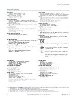
Wiring Diagrams for Analog Inputs

Connecting dc power to the communication pins will cause permanent damage. Do not exceed analog input ratings for

analog inputs. Only connect sensor outputs to analog inputs.

Analog Input Wiring (10–30 V dc Power)

Analog Input Wiring (4–20 mA, 2-Wire, Externally-

Powered Sensors)

Analog IN

PWR

10-30V dc

GND

+

sensor

dc common

Analog IN

GND

dc common

external power

+

sensor

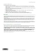
Wiring Diagrams for Analog Outputs

Connecting dc power to the communication pins will cause permanent damage.

Analog Output Wiring

AOx

GND

dc common

PWR

10-30V dc

sensor

LED Behavior for the Nodes

Nodes do not sample inputs until they are communicating with the Gateway. The radios and antennas must be a minimum

distance apart to function properly. Recommended minimum distances are:

2.4 GHz 65 mW radios: 1 foot
900 MHz 150 mW radios: 6 feet
900 MHz 1 Watt radios: 15 feet


Sure Cross

®

 Performance Node

6

www.bannerengineering.com - Tel: +1-763-544-3164

P/N 155862 Rev. G

Summary of Contents for Sure Cross DX80N9X6S-P2

Page 1: ...P2 900 MHz ISM Band IP67 NEMA 6 Inputs Four selectable discrete two 0 to 20 mA default or 0 to 10 V user configurable Outputs Four sourcing discrete two 0 to 20 mA DX80N2X6S P2 2 4 GHz ISM Band DX80 C...

Page 2: ...nstructions are not included in the datasheet refer to the product manual for binding instructions 5 Observe the LED behavior to verify the devices are communicating with each other For two LED models...

Page 3: ...A input allows you to determine when you have an error condition with the sensor A normal input reading between 4 and 20 mA indicates a functioning sensor whereas a value below 4 mA indicates an error...

Page 4: ...Refer to the Modbus Register table for the I O number for each analog input Writing a four 4 to the Units parameter defines the units as 0 to 10V Writing a two 2 to the Units parameter defines the un...

Page 5: ...x DOx Discrete OUT x GND Ground dc common connection PWR 10 to 30 V dc power connection RX Serial communication line for the Gateway No connection for Nodes TX Serial communication line for the Gatew...

Page 6: ...t damage Do not exceed analog input ratings for analog inputs Only connect sensor outputs to analog inputs Analog Input Wiring 10 30 V dc Power Analog Input Wiring 4 20 mA 2 Wire Externally Powered Se...

Page 7: ...de 16 Discrete IN 4 0 1 0 1 5 5 5 Node 16 Analog IN 1 mA V 0 0 0 0 20 0 10 0 0 65535 6 6 6 Node 16 Analog IN 2 mA V 0 0 0 0 20 0 10 0 0 65535 7 7 7 Node 16 Reserved 8 8 8 Node 16 Device Message 9 9 9...

Page 8: ...ications Certifications for DX8x C External Wiring Terminal and DX8x E Models CSA Class I Division 2 Groups ABCD Class I Zone 2 AEx Ex nA II T4 Certificate 1921239 ATEX II 3 G Ex nA IIC T4 Gc Group II...

Page 9: ...tion country is not on this list Any misuse abuse or improper application or installation of this product or use of the product for personal protection applications when the product is identified as n...

Reviews: