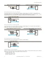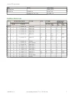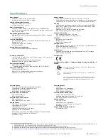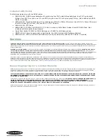
Transmit Power Levels
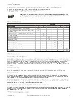
The 900 MHz radios can be operated at 1 watt (30 dBm) or 250 mW (24 dBm). While the Performance radios operate in 1
Watt mode, they cannot communicate with the older 150 mW radios. To communicate with the older 150 mW radios,
operate this radio in 250 mW mode. For 2.4 GHz models, this DIP switch is disabled. The transmit power for 2.4 GHz is
fixed at about 65 mW EIRP (18 dBm), making the 2.4 GHz Performance models automatically compatible with older 2.4
GHz models.
Configuring Universal Analog Inputs for mA or V
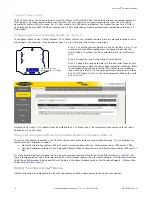
To configure inputs to use 0 to10V instead of 0 to 20mA, remove the installed resistors from the marked locations on the
wiring board. For example, to make analog input 1 a 0 to 10V input, follow these instructions.
G B − W +
A1
A2
A3
A4
Remove resistor in A1 slot
to make Analog IN 1 a 0–10V input.
Step 1. Cut out the resistor installed in the A1 (analog 1) slot. (Your
wiring board may differ slightly from the board shown. Use the
board's labels to confirm you have selected the correct resistor to
cut.)
Step 2. Launch the User Configuration Tool software.
Step 3. Change the units parameter for this particular input on this
device (Gateway or Node) to use voltage instead of milliamps. Refer
to the Modbus Register table for the I/O number for each analog
input. Writing a four (4) to the Units parameter defines the units as
0 to 10V. Writing a two (2) to the Units parameter defines the units
as 0 to 20 mA.
Note that a 220 ohm 0.1% resistor must be installed for a 0 to 20mA input. The resistor must be removed for an input
defined as a 0 to 10V input.
Using Performance and Non-Performance Radios in the Same Network
To comply with federal regulations, the 150 mW radios and 1 Watt radios communicate differently. To mix Performance
radios with non-Performance radios:
•
Operate Performance radios in 250 mW mode to communicate with non-Performance radios (DIP switch 1 ON)
•
Set non-Performance radios to use Extended Address Mode to communicate with Performance radios (DIP switch 1
ON)
more information about using Performance and non-Performance radios within the same network, refer the technical note
titled Mixing Performance Radios and 150 mW Radios in the Same Network listed on the Wireless Support - FAQs section
Wiring Your Sure Cross
®
Device
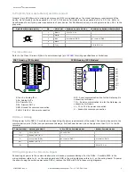
Use the following wiring diagrams to first wire the sensors and then apply power to the Sure Cross devices.
Sure Cross
®
Performance Node
4
www.bannerengineering.com - Tel: +1-763-544-3164
P/N 155862 Rev. G


