4.3.2 Initial Power-Up
1. Inspect the area near the light screen for reflective surfaces, including work pieces and the guarded machine.
Reflective surfaces may cause light beams to reflect around a person in the light screen, preventing the person
from being detected and not stopping the machine motion (see
Adjacent Reflective Surfaces
on page 16).
2. Eliminate the reflective surfaces as much possible by relocating, painting, masking, or roughening them. Remaining
problem reflections will become apparent during the trip test.
3. Verify that power is removed from the EZ-SCREEN Type 2 System and from the guarded machine and that the
OSSD safety outputs are not connected.
4. Remove all obstructions from the light screen.
5. Leaving power to the guarded machine Off, make power and earth ground connections on both the emitter and
receiver cables (see
Generic Emitter Wiring Diagram
on page 34).
6. Power up the EZ-SCREEN Type 2 System only.
7. Verify that the input power is present to both the emitter and the receiver. At least one indicator on both the
emitter and the receiver should be On and the start-up sequence should cycle.
8. Watch both the emitter and the receiver LED indicators to determine the light screen alignment status.
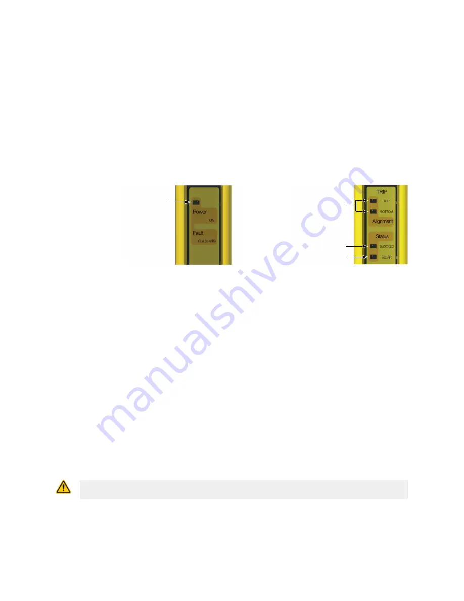
Power/Fault LED (Green)
Figure 12. Emitter Status Indicators
Alignment LEDs
(Yellow)
Status Blocked LED (Red)
Status Clear LED (Green)
Figure 13. Receiver Status Indicators
•
Lockout Condition—on the emitter, the green Power indicator is flashing or on the receiver, the red
Status Blocked indicator is flashing. See
Troubleshooting and Lockout Conditions
on page 40 for
diagnostic information.
•
Normal Operating Mode—to the emitter, the green Power indicator is ON.
•
Test Mode, input fault: On the receiver, the red Status Blocked indicator is On and the green Status Clear
indicator is On. Test input open at power-up.
•
Receiver Latch Condition, all optical beams clear—on the receiver, the red Status Blocked indicator is
On and both yellow Alignment indicators are flashing. For Latch Output receivers, the outputs are On only
when all beams are clear and after a manual reset. If a reset routine can cause a Clear (Run) condition,
optimize the alignment as described in
Optical Alignment
on page 26. If a Clear (Run) condition cannot be
achieved, see “Blocked condition” below.
•
Clear (Run) Condition—on the receiver, the green Status Clear indicator is On Green, and both yellow
Alignment indicators are On. To optimize alignment and maximize excess gain, slightly loosen the four
sensor mounting screws and rotate one sensor left and right, noting the positions where the red Status
Blocked indicator turns On; repeat with the other sensor (see
Optical Alignment
on page 26). Center each
sensor between those two positions and tighten the end cap mounting screws, making sure to maintain the
positioning as the screws are tightened. The sensor lenses should directly face each other. Proceed to
Trip
Test
on page 28 once optimum optical alignment is verified.
•
A Blocked Condition—on the receiver, the red Status Blocked indicator is On, and both yellow Alignment
indicators are On or Off. To remedy, perform the
Optical Alignment
on page 26 procedure.
4.3.3 Optical Alignment
CAUTION: Ensure that no individuals are exposed to any hazard if the OSSD outputs turn ON
when the emitter and receiver become aligned.
EZ-SCREEN
®
Type 2 Light Screen
Phone: 800.894.0412 - Fax: 888.723.4773 - Web: www.clrwtr.com - Email: [email protected]


