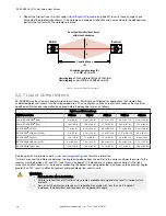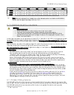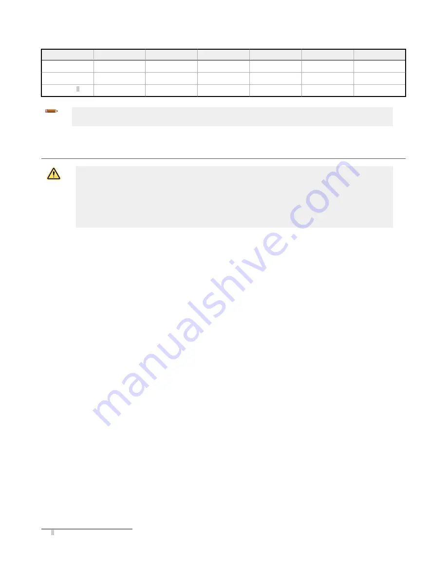
Table 2: Maximum Machine Interface cable length versus total current draw (including both OSSD loads)
0.5 A
0.75 A
1.0 A
1.25 A
1.5 A
1.75 A
18 AWG
114.3 m (375 ft)
76.2 m (250 ft)
57.3 m (188 ft)
45.1 m (148 ft)
38.1 m (125 ft)
33.2 m (109 ft)
20 AWG
73.1 m (240 ft)
48.8 m (160 ft)
36.6 m (120 ft)
30.0 m (95 ft)
24.4 m (80 ft)
21.3 m (70 ft)
22 AWG 3
45.7 m (150 ft)
30.5 m (100 ft)
22.9 m (75 ft)
18.0 m (59 ft)
15.2 m (50 ft)
13.4 m (44 ft)
Note: Maximum cable lengths are intended to ensure that adequate power is available to the EZ-SCREEN
System when the supply is operating at +24 V dc – 15%.
5.7 Initial Electrical Connections
WARNING:
• Risk of electric shock
• Failure to follow these instructions could result in serious injury or death.
• Disconnect or turn off power before installing, removing, or servicing the device.
• Install and connect the device in accordance with the National Electrical Code (NEC) and any
applicable local code requirements and supply the device with an appropriate fuse box or circuit
breaker (see
Specifications
).
Lockout/tagout procedures may be required (refer to OSHA1910.147, ANSI Z244-1, ISO 14118, or the appropriate standard
for controlling hazardous energy). Following relevant electrical standards and wiring codes, such as the NEC, NFPA79 or
IEC60204-1, always connect the earth ground (green/yellow wire). Do not operate the EZ-SCREEN without an earth ground
connection.
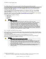
Make the electrical connections in the order described in this section. Do not remove end-caps; no internal connections are
to be made. All connections are made through the M12 Euro-style quick-disconnects.
When installing QD cables, do not use tools to tighten the coupling nut—hand-tighten only. Do not rotate the body of the
QD, or damage to the connector can occur.
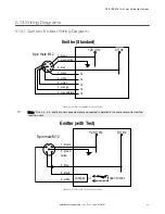
Emitter Cordset
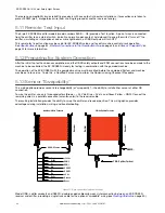
EZ-SCREEN emitters have an 8-pin cordset, but not all conductors are used. The unused wires are in place to
allow a parallel connection (color-for-color) to the receiver cable providing sensor interchangeability (or
“swapability”); either sensor may be installed at either cordset connection. In addition to providing similar cabling,
this wiring scheme is advantageous during installation, wiring, and troubleshooting.
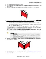
Emitters with the optional TEST function (model number suffix Q5) use a 5-pin cable. Locate the black and the
white wires at the cable end; if the Test input will be used, temporarily connect the ends of the wires to each other
(but not to an external contact at this time). If the Test input will not be used, connect the emitter cable black and
white wires together and properly terminate (for example, with the included wire-nut).
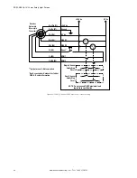
Receiver Cordset
Do not connect any wires to the machine control circuits (that is, OSSD outputs) at this time. For the initial power-
up and checkout, normally open EDM must be configured. Locate the orange and orange/black wires (pins 2 and 3)
and temporarily connect the ends of the wires to each other (but not to the machine at this time). Take precautions
to prevent the wires from shorting to ground or to other sources of energy (for example, terminate with the included
wire-nut). Final EDM wiring must be completed later.
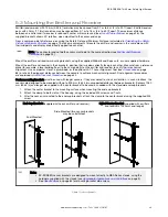
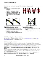
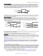
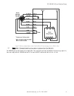
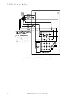
If used, connect the external reset switch to the reset wire (violet) on the receiver cable and to 24 V dc (see
on page 46). See the warning in
on page 23 about the
physical location of the reset switch. The reset switch must be a normally open switch that is held closed for
approximately 1/4 second, but no longer than 2 seconds, and then re-opened to accomplish the reset. The switch
must be capable of switching 10 V dc to 30 V dc at 30 mA.
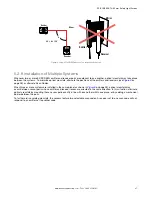
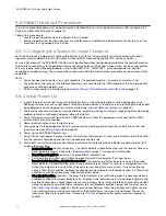
5.7.1 Emitter Wiring Options
An EZ-SCREEN emitter with an 8-pin connector can be connected either to its own power supply or to the receiver cable,
color-for-color. The color-for-color connection allows the emitter and receiver positions to be interchanged without rewiring.
An EZ-SCREEN emitter with an 5-pin connector and Test function is not capable of the color-for-color connection.
3 QDE-...D cables, see
EZ-SCREEN
®
14/30 mm Safety Light Screen
www.bannerengineering.com - Tel: + 1 888 373 6767
31

