background image

The event counter is active for RF firmware revision 5.3 or higher.

 In the default position (OFF), the input 1 through 6 control the

tower lights. When DIP switch 3 is ON, input 5 wire is the counter input and input 6 wire is disabled. Registers 5 and 6 store the 32-

bit synchronous counter count. Inputs 5 and 6 are independent from the lights and will not drive any lights they are wired to. Input

wires 1 through 4 function normally.

DIP Switch 3: Event Counter

900 MHz Models and 2.4 GHz Models

OFF *

Default I/O operation

ON

8-pin Models: Configure input 5 as a 32-bit synchronous counter at a maximum frequency of 20 Hz; disable
input 6 (the counter requires two registers)

5-Pin Models: Configure input 3 as a 32-bit synchronous counter at a maximum frequency of 20 Hz

The event counter is active for RF firmware revision 5.3 or higher.

For the 8-pin models: In the default position (OFF), inputs 1 through 6 control the tower lights. When DIP switch 3 is ON, input 5

wire is the counter input and input 6 wire is disabled. Registers 5 and 6 store the 32-bit synchronous counter count. Inputs 5 and 6

are independent from the lights and will not drive any lights they are wired to. Inputs 1 through 4 function normally.
For the 5-pin models: In the default position (OFF), inputs 1 through 3 control the tower lights. When DIP switch 3 is ON, input 3

wire is the counter input. Registers 3 and 4 store the 32-bit synchronous counter count. Input 3 is independent from the lights and

will not drive any lights they are wired to. Inputs 1 and 2 function normally.

DIP Switch 4: Bit Packing I/O

900 MHz Models and 2.4 GHz Models

OFF *

Default I/O operation

ON

Bit-packed I/O with all inputs in Modbus register 1 and all outputs in Modbus register 9. All other Modbus
registers are disabled.

Bit packing is active for RF firmware revision 5.8 or higher.

 Bit packing uses a single register, or range of contiguous registers, to

represent I/O values. This allows you to read or write multiple I/O values with a single Modbus message. Input 1 is stored in the

least significant bit of register 1. Output 1 is stored in the least significant bit of register 9.
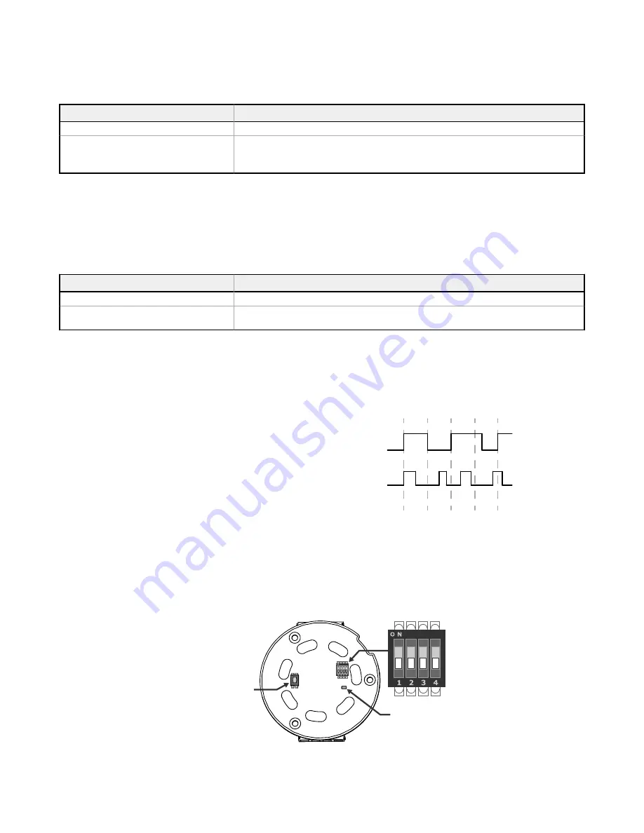
Event Counter

To use the event counter, the measured (logic high) signal must be greater
than or equal to 25 ms. The 32-bit count is stored in I/O registers 5 and 6.

To zero out (clear) the event counter,

Map an input/button on a Gateway to Node register 14 to clear the

counter when the input/button is activated; or

From a host system, write a 1 (the output must transition from a zero

to a one to reset the counter) to Node register 14 or write a 5424

(0x1530) to Node control register 15.

RF firmware revision 5.3 or higher (on all products released after 3/20/2015) is

required to use this feature.

Correct

Incorrect

t = 0

25 ms 50 ms 75 ms 100 ms

Bind the K70 to the Gateway and Assign the Node Address

Before beginning the binding procedure, apply power to all the devices.
 

DIP Switches

Binding

Push Button

LED


EZ-LIGHT

®

 K70 Wireless Indicator Light

4

www.bannerengineering.com - Tel: + 1 888 373 6767

P/N 192534 Rev. D

Summary of Contents for EZ-LIGHT K70 Series

Page 1: ...talación de estos dispositivos Important Veuillez télécharger la documentation technique complète des K70 Wireless Indicator Light sur notre site www bannerengineering com pour les détails sur leur utilisation correcte les applications les notes de sécurité et les instructions de montage Models 900 MHz Models Model No of Colors Colors Connection K70DXN9RQ 1 Red Integral 5 pin M12 Euro style male q...

Page 2: ...lock into place notches shown in locked position Wiring Sourcing PNP Input Euro style Male Pinouts Key Module C2 C3 C1 3 4 1 2 5 12 30 V dc 1 4 5 3 2 1 brown 2 white 3 blue 4 black 5 gray C1 Module 1 C2 Module 2 C3 Module 3 EZ LIGHT K70 Wireless Indicator Light 2 www bannerengineering com Tel 1 888 373 6767 P N 192534 Rev D ...

Page 3: ...nsmit at 1 Watt 30 dBm or 250 mW 24 dBm While the Performance radios operate in 1 Watt mode they cannot communicate with the older 150 mW radios To communicate with 150 mW radios operate this radio in 250 mW mode For 2 4 GHz models this DIP switch is disabled The transmit power for 2 4 GHz is fixed at about 65 mW EIRP 18 dBm making the 2 4 GHz Performance models automatically compatible with older...

Page 4: ...r count Input 3 is independent from the lights and will not drive any lights they are wired to Inputs 1 and 2 function normally DIP Switch 4 Bit Packing I O 900 MHz Models and 2 4 GHz Models OFF Default I O operation ON Bit packed I O with all inputs in Modbus register 1 and all outputs in Modbus register 9 All other Modbus registers are disabled Bit packing is active for RF firmware revision 5 8 ...

Page 5: ...e click button 2 For board level modules double click the button For DXM models click BACK until you return to the main menu LED Behavior for the Nodes Nodes do not sample inputs until they are communicating with the Gateway The radios and antennas must be a minimum distance apart to function properly Recommended minimum distances are 900 MHz 150 mW and 250 mW radios 6 feet 900 MHz 1 Watt radios 1...

Page 6: ...own below to achieve this flash pattern Flash a K70 light by entering a time based bit mask into the Duty Cycle parameter for that output register Bit 0 represents the first 62 5 ms time window bit 1 represents the second 62 5 ms window etc For example turn ON the output from 0 to 250 ms OFF from 250 to 500 ms ON from 500 to 750 ms then OFF again from 750 ms to 1 second by writing 0x0F0F to the ap...

Page 7: ... 525 nm 65 Red 625 nm 34 Yellow 590 nm 22 Blue 470 nm 22 White 5000 K 87 Indicators 1 to 5 colors depending on model Green Red Yellow Blue and White Connections 5 pin M12 Euro style quick disconnect 8 pin M12 Euro style quick disconnect 150 mm 5 9 in PVC cable with an M12 Euro style quick disconnect or 2 m 6 5 ft unterminated cable depending on model Operating Conditions 40 C to 50 C 40 F to 122 F...

Page 8: ... Link Timeout Gateway Configurable via User Configuration Software Node Defined by Gateway Dimensions All measurements are listed in millimeters inches unless noted otherwise Dimensions for the quick disconnect model are shown Accessories Cordsets 5 Pin Threaded M12 Euro Style Cordsets Single Ended Model Length Style Dimensions Pinout Female MQDC1 501 5 0 50 m 1 5 ft Straight 44 Typ ø 14 5 M12 x 1...

Page 9: ...nsor 70 57 A B C 57 Hole center spacing A 51 A to B 25 4 Hole size A 42 6 x 7 B ø 6 4 C ø 30 1 SMBAMS30P Flat SMBAMS series bracket 30 mm hole for mounting sensors Articulation slots for 90 rotation 12 ga 300 series stainless steel 45 93 A C B Hole center spacing A 26 0 A to B 13 0 Hole size A 26 8 x 7 0 B ø 6 5 C ø 31 0 SSA MBK EEC1 Single 30 mm hole 8 gauge steel black finish powder coat Front s...

Page 10: ...nects between in NPSM DN15 pipe and 30 mm 1 3 16 in drilled hole Mounting hardware included SA E12M30C White UHMW Pipe Mounting Flange Model Features Construction SA F12 Elevated use stand off pipes in NPSM DN15 M5 mounting hardware and nitrile gasket included Die cast zinc base with black paint 10 ø28 ø70 1 2 14 NPSM 4x ø5 5 54 Foldable Mounting Brackets Model Features Construction SA FFB12 For u...

Page 11: ...nner Engineering Corp will void the product warranties All specifications published in this document are subject to change Banner reserves the right to modify product specifications or update documentation at any time Specifications and product information in English supersede that which is provided in any other language For the most recent version of any documentation refer to www bannerengineeri...

Reviews: