


1
© Banner Engineering Corp. www.bannerengineering.com
IO-L
INK
O
VERVIEW
1. IO-Link Overview
IO-Link is an open standard serial communication protocol that allows for the bi-directional exchange of data from IO-Link-supported devices,
such as sensors, that are connected through IO-Link.
Advantages to an IO-Link system include standardized wiring, remote configuration, simple device replacement, advanced diagnostics, and
increased data availability. Because IO-Link is an open standard, the devices can be integrated in almost any fieldbus or automation system.
An IO-Link system consists of an IO-Link master and an IO-Link device such as a sensor, lighting product, IO-Link hub, or actuator.
The functions and parameters of the IO-Link devices are represented in a device description file (IODD). IODD files contain information about
identification, device parameters, process and diagnostic data, communication properties, and other details. The IODD files for Banner IO-link
devices can be downloaded for free on
1.1. IO-Link Systems
At least one IO-Link master and one IO-Link device are required for IO-Link communication.
The IO-Link master and IO-Link device are connected using a 3-wire standard unshielded cable. The IO-Link master establishes the connection
between IO-Link device and the higher-level control system. An IO-Link master can have several IO-Link ports, and only one IO-Link device can
be connected to each port.
IO-Link hubs such as Banner's
R90C-4B21-KQ
or IO-link converters make it possible to integrate devices without an IO-Link output in automation
systems via IO-Link.
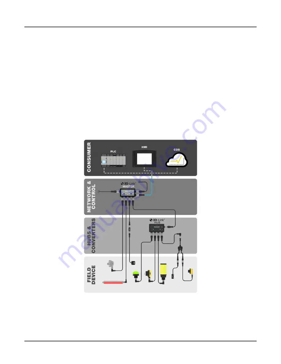
Figure 1:
IO-Link map
1.2. IO-Link Port/Operating Modes
The operating mode can be configured for any port on the IO-Link master. The following modes can be used:


