


•
Severe contamination/changes in the taught condition can prevent the Auto Thresholds algorithm from optimizing
the threshold(s). If this occurs, the DF-G2 enters a Threshold Alert or Threshold Error state. See
on page 21 for more explanation.
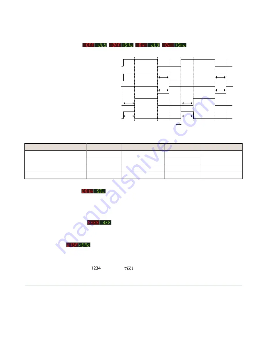
3.2.5 Delays/Timers
ON/OFF Delays and ON/OFF One-Shot
timers can be programmed between 1 -
9999 ms (a value of 0 disables the delay/
timer).
on page 10 defines how
the delays/timers affect the output
behavior.
Some combinations of delays/timers are not
allowed. The DF-G2 programming menu
automatically disables invalid combinations
of delays/timers. The following table shows
the allowable combinations of delays/
timers:
Output
OFF Delay
ON Delay
Time
OFF 1-Shot
ON 1-Shot
ON
OFF
D
D
D
D
D
D
D
D
(D = 1 - 9999 ms)
Figure 3. DF-G2 Delays/Timers
OFF Delay
OFF One-Shot Timer
ON Delay
ON One-Shot Timer
OFF Delay
-
OK
OK
N/A
OFF One-Shot Timer
OK
-
N/A
N/A
ON Delay
OK
N/A
-
OK
ON One-Shot Timer
N/A
N/A
OK
-
3.2.6 Gain Selection
The DF-G2 can operate in Auto Gain mode or the Gain can be fixed to be in Gain 1...8. In Auto Gain, the DF-G2 optimizes
the gain during a TEACH/SET method for the presented condition(s). While viewing the fixed gains in the Gain Selection
choice list, the DF-G2 will automatically switch to the selected gain and display the measured signal on the Red display.
This allows for easy and quick evaluation of the fixed gain mode.
3.2.7 Factory Defaults
The Factory Defaults menu allows the DF-G2 to be easily restored back to original factory default settings (see Factory
Default Settings in Specifications).
Display Readout
The readout of the digital displays can be programmed for the following options:
•
Signal/Threshold readout - Numeric (1234) or % (123P)
•
ECO mode - Enabled or Disabled (ECO mode dims the displays to reduce current consumption)
•
Display Orientation - Normal (
) or Flipped (
)
3.3 Remote Input
The remote input may be used to perform TEACH/SET methods and to program the sensor remotely. Connect the white
input wire of the sensor to ground (0 V dc), with a remote switch connected between them. Pulse the remote input
according to the diagram shown in
on page 11. Follow the instructions in the TEACH/SET sections in
on page 12 to perform a TEACH/SET method.
The sensor exits TEACH and remote programming modes after a 60 second timeout. Users may exit TEACH and remote
programming modes by setting the remote input low for more than 2 seconds. In either case, the sensor returns to Run
mode without saving any new settings.
DF-G2 High Speed Expert
™
Dual Display Fiber Amplifier
10
www.bannerengineering.com - Tel: 763.544.3164