


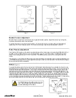


Mandrel Tension Adjustment
Mandrel tension must be set correctly to ensure good lamination quality. Adjust the tension by turning the
knurled knobs at both ends of the mandrels.
To tighten the tension, turn the knobs clockwise. To loosen the tension, turn the knobs counterclockwise.
Adjust only 1/8 of a turn between tests. Too much tension may cause the laminating film to stretch.
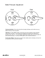
Roller Pressure Adjustment
The Finisher 2700 gives you the option to automatically set the roller pressure by selecting OPEN, MOUNT, or
CLOSE. In the CLOSE position you can laminate items up to 1/8” (3.175mm) thick. The MOUNT position
allows for mounting items up to ½” (12.7mm) thick. The OPEN position is used for removing film from the
rollers.
The pressure on your Finisher 2700 has been preset at the factory and should require no manual adjustment. If
you find that the pressure does require adjustment, please contact our Roll Laminator Technical Service Depart-
ment at 909-296-9780 for assistance.
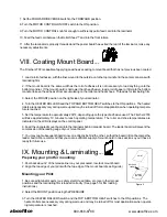
Slitters
(Figure 3)
To install the slitters, place the mounts into the TOP ROLLER GUARD where they will slide into the slot in the
GUARD top edge, located at the end of the GUARD. Before setting the slitters in place, ensure the machine is
loaded with the proper laminating film. Use a piece of paper/card stock the same width as the product to be
laminated to feed into the laminator until it has exited several inches beyond the TOP ROLLER GUARD. This
will permit accurate placement of the slitters. Locate the two BLADE HOLDERS. The blade holder is a square
shaped bar with a blade in one end. Place the holder, blade down, into the mount until the blade. barely pen-
etrates the plastic web at the edge of the test piece leaving the required border beyond the edge. Ensure the
point of the blade is pointed toward the front of the laminator. Tighten both screws on the mount. To ensure the
mount and holder won’t move from side to side, use an Allen wrench to tighten the screws.
CAUTION: Remove the slitter when it is not in
use. This will help prevent personal injury or
accidental damage to the rollers.
6
Figure 1
Figure 2
BA-FS27 Threading Diagram
for Poly-in Rolls
BA-FS27 Threading Diagram
for Poly-out Rolls
Figure 3
Slitter
Knob
Slitter Adjustment
Knob (5/16-18 cap
screw)
Slitter Assy.
Mount
Screw
(5/16-18
cap screw)
Slitter Main
Body Clamp
Slitter Blade
Slitter
Blade
Holder
abcoffice
800-658-8788


