


97654 v.7
49
11.4.2 MANUAL Mode
In MANUAL Mode, the SpeedBrake will
activate, downshift the transmission, and
adjust the turbocharger vanes, resulting
in a braking effect that attempts to
slow your vehicle to 15 mph (24 km/h).
MANUAL Mode has three strength
selections available: "
HIGH
", "
MED
"
(medium) and "
LOW
."
"
HIGH
" strength achieves the highest
level of braking force by aggressively
downshifting the transmission and
closing the turbocharger vanes. This
setting is recommended for heavily
loaded vehicles or whenever aggressive
braking is desired.
"
MED
" (medium) strength achieves
a moderate level of braking force by
slightly delaying transmission downshifts.
This setting is recommended for
moderately loaded vehicles.
"
LOW
" strength setting achieves a
lower level of braking force and is
recommended for lightly loaded or
unloaded vehicles. The "
LOW
" setting
may also be used for daily driving.
11.4.3 AUTO Mode
AUTO Mode uses various functions
of the Banks SpeedBrake to keep the
vehicle at the driver’s set target speed.
When AUTO Mode is active and the
vehicle is above the targeted speed, the
Banks SpeedBrake will slow the vehicle
to the targeted speed and maintain it.
The Banks SpeedBrake will become
inactive as soon as the vehicle drops
below the target speed.
11.4.4 Foot Brake
Activation
The SpeedBrake's Foot Brake feature
provides additional braking while using
your vehicle's brakes at vehicle speeds
greater than 15 mph (24 km/h).
When switching between different
modes, the Foot Brake feature will
remain in the setting last implemented.
When in MANUAL Mode
, the Foot
Brake feature allows you to limit
SpeedBrake activation to
ONLY
when
you press the brake pedal at vehicle
speeds greater than 15 mph (24 km/h).
If your vehicle speed is under 15 mph
(24 km/h), the SpeedBrake will stop
providing additional braking.
If the Foot Brake feature is disabled,
while in Manual Mode, the SpeedBrake
will activate after releasing the accel
pedal at vehicle speeds above 15 mph
(24 km/h), regardless of whether or not
the brake pedal is used.
When in AUTO Mode,
the Foot Brake
feature will not affect the automatic
braking above the set speed. Below
AUTO Mode's set speed, the Foot Brake
feature provides additional braking while
using your vehicle's brakes at vehicle
speeds greater than 15 mph (24 km/h)
BANKS MODULES (IF CONNECTED),
CONTINUED
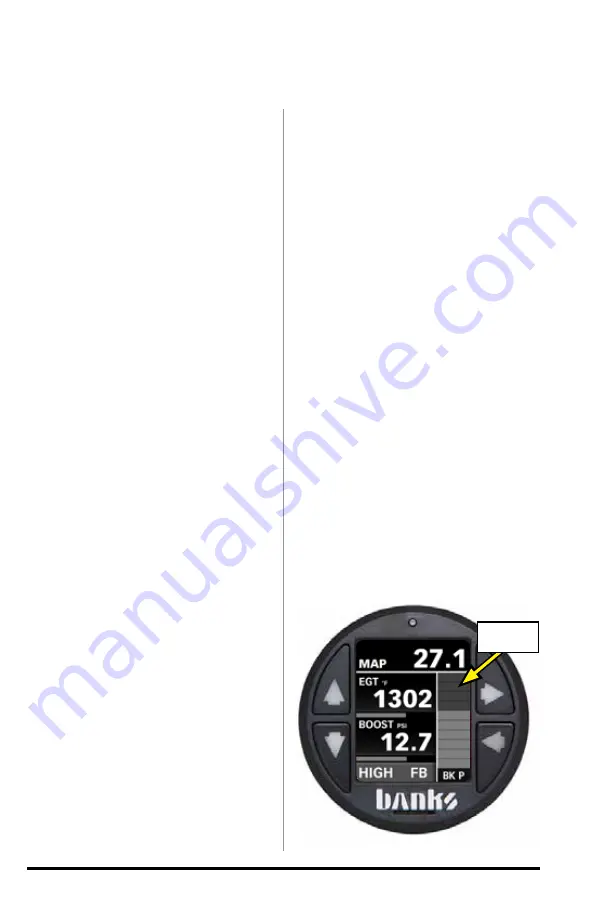
Figure 11-6
BK P
HIGH FB
% Braking
Strength
Summary of Contents for iDash 1.8
Page 3: ...97654 v 7 3...


