Bang&Oiufsen
•
Playback frequency path
Bias oscillator
•
Bias filter
e
Record lift
•
•
6-2
30Hz
250Hz 1kHz
6,3kHz
15kHz
5
d
B
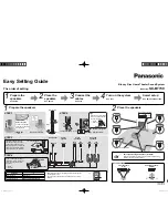
Activate Cr02 button.
Test
playback
frequency path with test tape 6 780056 to be within
ab
o
v
e
framework.
Treble level
js
adjustable
by
means of 12C209 (12C109). With 12C209
(12C109) fitted there
will
be treble lift, without 12C209 (12Cl09) there
will
b
e
treble cut.
R
2
13
@
12
P.B.----REC
C201 CI01
B
a
1
s Level
R24
\�@@
TP4 .
TP3
B��s
Frl'q
C230
®
L203 LIOJ
All
L202@@LXl2
Rec.Baast
-CJ-
Aec. Currt>rt
Rec.Current
Fe A
A<'C
.
Curr..nt
Fe l
R113
Cl��I-�R101
--.J::! -AtiO-'l
A201
' ,
Connect frequency counter or oscilloscope to 12R201.
Activate Rec. Pause.
Check that the bias frequency is approx. 105kHz (approx. 9 �secs.).
Make adjustments,
it aPy,
with 12Ll.
Activate Rec. Pause.
Adjust 12L203 (12Ll03) to minimum deflection as measured with an AF
voltmeter in 12TP4 (12TP3).
Stop the bias oscillator by disconnecting 12R5.
Activate Rec. Pause.
Connect a tone generator to the tape input and set it to deliver 333
Hz in
the
1
V
range.
Adjust the record potentiometer until 3 m
V
is measured with an AF voltmeter
across 12R201 (12R101).
Set the tone generator at 10 kHz.
Adjust 12L202 (12Ll02) until? m
V
is measured across 12R201 (12R101).
Start the bias oscillator.
•
•
e
e
Bang&Oiufsen
Channel separation
AM-IF
Connect the stereo decoder to the aerial input.
Connect a wattmeter or an AC voltmeter to the AF output.
Adjust with 2R54 to max. channel separation (better than 30 dB).
Set the receiver at, e.g., 1,600 kHz.
Adjust the sweep generator to 468 kHz and connect it to 3TP1.
Connect an oscilloscope to 3TP2.
Adjust 3L5 and 3L6 to max. and symmetrical IF curve.
5-2
Parallel-series trap
Connect a signal generato,r to the aerial input via a dummy aerial and adjust the
generator to 468 kHz, mod. 3b% 400 Hz.
Set the receiver at 575kHz.
Connect a wattmeter or an AC voltmeter to the AF output.
Adjust 3L3 and 3L4 to minimum.
MW
oscillator and aerial circuits
Connect a signal generator to the aerial input via a dummy aerial and adjust the
generator to 575kHz, mod. 30% 400 Hz.
LW
oscillator and aerial circuits
Set the receiver at 575 kHz.
Connect a wattmeter or an AC voltmeter to the AF output.
Adjust the oscillator with 4L2 until it is centered on the transmitting frequency.
Adjust the serial circuit with 3L2 to max. output.
Adjust the receiver and the signal generator to 1495kHz.
Adjust the oscillator with 4C8 until it is centered on the transmitting frequency.
Adjust the aerial circuit with 3C4 to max. output
Adjust the receiver and the signal generator to 155kHz.
Adjust the oscillator with 4Ll until it is centered on the transmitting frequency.
Adjust the aerial circuit with 3Ll to max. output.
Adjust the receiver and the oscillator to 320 kHz .
Adjust the aerial circuit with 3C3 to max. output.
Summary of Contents for BEOCENTER 2000
Page 1: ......
Page 14: ...Bang Oiufsen 18100 18101 I _ 18158 4 4 18151 18152 ...