


Commissioning
44
Power Panel C50 User's manual V1.10
5.1.5 Grounding (functional ground)
Disturbances are discharged effectively via a grounding clip. For additional information about electromagnet-
ic compatibility, see the
INSTALLATIONS / EMC GUIDE
user's manual (MAEMV-ENG on the B&R website
).
Notice!
Possible malfunction of interfaces and touch screen!
If functional ground is not present, faults in interface communication and touch screen functionality
can occur.
The device is only permitted to be operated if properly grounded.
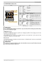
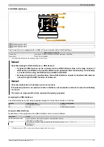
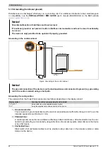
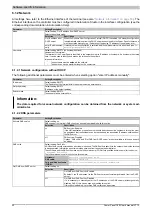
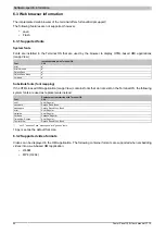
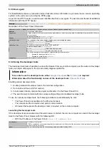
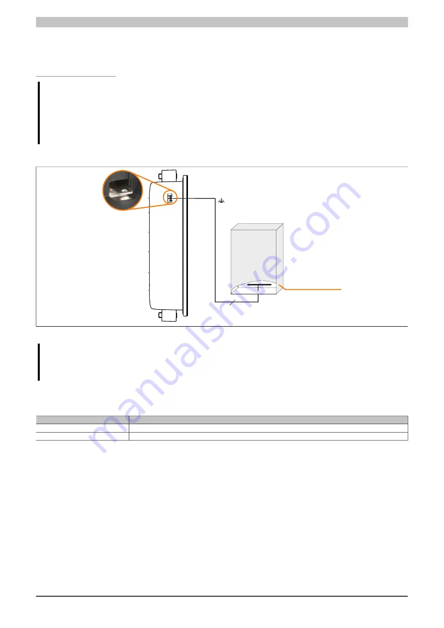
Grounding in the control cabinet
Control cabinet
Grounding rail
Ground connection
≥4 mm²
Figure: Grounding in the control cabinet
Notice!
The ground connection of the device must be low impedance and connected to ground (e.g. grounding
rail in the control cabinet) using a short path.
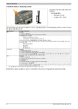
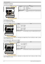
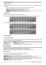
Grounding / Securing cables
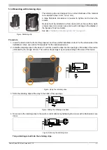
The cables to/from the Power Panel are secured as follows depending on the display variant:
Display variant
Securing the cables and grounding the cable shield
7.0" to 121"
Using cable ties on the supplied accessory plate
15.6"
Using the supplied cable clamps directly on the device
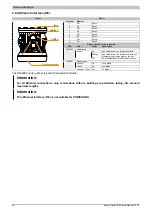
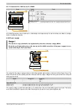
1)
Ground conductor
The connection to ground potential must be as short as possible and sufficiently strong (≥4 mm²) over the
intended spade terminal (Faston 6.3 mm).
2)
Shielded lines
A central ground connection is available to effectively deflect interference. All cable shields must be con-
nected to ground with good conductivity using cable ties on the accessory plate, cable clamps on the device
or by other means.
3)
Unshielded lines
Strain relief of all unshielded cables must be provided using cable ties on the accessory plate or cable
clamps on the device.


