background image

Accessories  • CompactFlash cards

Chapter 6 Accessories

Power Panel 500 user's manual V1.40

263

3)

Endurance of B&R CFs (with linear written block size ≥128 kB).

4)

Depends on the average file size.

5)

Not supported by the B&R Embedded OS Installer.

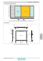
4.4.4 Temperature/Humidity diagram

Temperature [°C]

R

elat

ive 

hum

id

ity 

[%

R

H

] (no

n-cond

en

sing

)

Storage

Transport

Operation

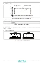
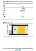
Figure 145: 5CFCRD.xxxx-04 - Temperature/Humidity diagram for CompactFlash cards

4.4.5 Dimensions

Above

26

50

1

25

1.01 ±0.07

1.01 ±0.07

1.

60 

±0.

05

0.

99 

±0.

05

4x R0.5 ±0.1

3.30 ±0.1

2x 

12 

±0.

10

2x 

 25.

78 

±0.

07

1.65

42.8 ±0.1

41.66 ±0.13

36.

±0.

15

2x 

±0.

07

2.44 ±0.07

0.

76 

±0.

07

0.63 ±0.07

CompactFlash Type I

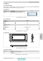
Figure 146: Type I CompactFlash card - Dimensions

Summary of Contents for Power Panel 500 Series

Page 1: ...e of publication however Bernecker Rainer Industrie Elektronik Ges m b H makes no warranty ex pressed or implied with regard to the products or documentation contained within this manual In addition B...

Page 2: ...Chapter 1 General information Chapter 2 Technical data Chapter 3 Installation Chapter 4 Software Chapter 5 Standards and certifications Chapter 6 Accessories Chapter 7 Maintenance and service Appendix...

Page 3: ...PC 18 1 3 A complete solution with maximum flexibility 19 1 4 Open system platform 19 1 5 Features 19 1 6 System components Configuration 20 1 6 1 Configuration Base system 20 1 6 2 Configuration Sof...

Page 4: ...1 Procedure 131 1 4 Mounting orientations 133 1 4 1 Mounting orientation 0 133 1 4 2 Mounting orientation 45 134 1 4 3 Mounting orientation 90 135 1 4 4 Mounting orientation 90 vertical 136 1 4 5 Mou...

Page 5: ...5 1 2 BIOS Setup and boot procedure 155 1 2 1 BIOS Setup keys 157 1 3 Main 158 1 4 OEM features 159 1 4 1 CPU board features 160 1 4 2 System unit features 165 1 4 3 I O board features 169 1 4 4 IF bo...

Page 6: ...222 4 6 Special considerations limitations 222 4 7 Supported display resolutions 222 5 Windows Embedded Standard 2009 223 5 1 General information 223 5 2 Order data 223 5 3 Overview 223 5 4 Features...

Page 7: ...tandards and guidelines 244 1 1 CE mark 244 1 2 EMC directive 244 1 3 Low voltage directive 244 2 Certifications 245 2 1 UL certification 245 2 2 GOST R 245 2 3 GL certification Germanischer Lloyd 245...

Page 8: ...nterfaces 269 5 1 4 Technical data 269 5 1 5 Dimensions 271 5 1 6 Dimensions with front cover 271 5 1 7 Cutout installation 272 5 1 8 Content of delivery 272 5 1 9 Installation 272 5 2 5A5003 03 273 5...
Page 9: ...ng 282 2 Replacing the battery 283 2 1 Evaluating the battery status 283 2 2 Procedure 283 3 Replacing a CompactFlash card 284 Appendix A 286 1 Maintenance Controller Extended MTCX 286 2 5 wire AMT to...

Page 10: ...d automatically if a BIOS update error occurs Updated section 8 Automation Runtime on page 230 in 4 Software Updated maximum specified temperatures of temperature sensors in section 2 1 2 Temperature...

Page 11: ...ed new CompactFlash cards 8 GB in Accessories on page 248 Added USB media drive on page 269 Revised chapter Standards and certifications on page 244 Updated all technical data Updated section Serial n...

Page 12: ...dling Electrical components with a housing Do not touch the connector contacts on connected cables Do not touch the contact tips on circuit boards Electrical components without a housing The following...

Page 13: ...connections 2 6 Operation 2 6 1 Protection against touching electrical parts To operate programmable logic controllers operating and monitoring devices and uninterruptible power supplies certain compo...

Page 14: ...ials It is necessary to separate different materials so the device can undergo an environmentally friendly recycling process Component Disposal Programmable logic controllers Operating Monitoring devi...

Page 15: ...ge to equipment Caution Disregarding these safety guidelines and notices can result in injury or damage to equipment Information This information is important for preventing errors Table 3 Description...

Page 16: ...mpactFlash 1 GB B R SLC 261 5CFCRD 2048 03 CompactFlash 2 GB Western Digital SLC 265 5CFCRD 2048 04 CompactFlash 2 GB B R SLC 261 5CFCRD 4096 03 CompactFlash 4 GB Western Digital SLC 265 5CFCRD 4096 0...

Page 17: ...91 77 Systemeinheiten 5PP520 0702 00 Power Panel 520 7 WVGA TFT display with touch screen resistive connections for 1x RS232 2x USB 2 0 1x Ethernet 10 100 1000 can be expanded with interface board IP6...

Page 18: ...nected to various automation infrastructures Compact Power Panel devices are designed for use in the harshest industrial environments and ensure the highest level of operating comfort Uniform project...

Page 19: ...access for operating personnel and ensures that process information is available on the machine where it is needed 1 4 Open system platform In addition to enabling the implementation of complete autom...

Page 20: ...board Select 1 Select 1 System unit Configuration Base system CPU board Main memory Select 1 Main memory A system unit consists of a housing and a display Variants 00 01 PP500 with slot for Interface...

Page 21: ...4096 06 5MMUSB 2048 01 5MMUSB 4096 01 Software Select 1 each Select 1 Terminal blocks 0TB103 9 0TB103 91 5SWWI7 1100 ENG 5SWWI7 1100 GER 5SWWI7 1300 MUL Windows 7 Windows XP 5SWWXP 0600 ENG 5SWWXP 060...

Page 22: ...as the amount of main memory It is also possible to insert interface boards and in some devices devices whose model number ends in 01 e g 5PP5xx xxx 01 I O boards For additional information about con...

Page 23: ...ing worst case conditions Thermal Analysis Tool TAT V2 02 from Intel for simulating a 100 processor load BurnInTest tool BurnInTest V4 0 Pro from Passmark Software for simulating a 100 load on the int...

Page 24: ...in the processor 100 C 5PP5CP US15 00 5PP5CP US15 01 90 C 5PP5CP US15 02 A Main memory Ambient temperature of the main memory sensor integrated in the processor 80 C B Interfaces Temperature of the in...

Page 25: ...P5IF FETH 00 5 to 90 5 to 95 5PP5IF FPLM 00 5 to 90 5 to 95 5PP5IF FCAN 00 5 to 90 5 to 95 5PP5IF FCAN 00 5 to 90 5 to 95 5PP5IF FX2X 00 5 to 90 5 to 95 Interface boards 5PP5IF FXCM 00 5 to 90 5 to 95...

Page 26: ...4 VDC Capacitors for min 10 ms 3V3 standby 3V3 3V3 5 V 15 V 5 V 15 V Power button on 5 V standby electrically isolated Figure 4 Supply voltage for system units Description 15 V is generated from the s...

Page 27: ...ents and serial number sticker for the System unit Serial number sticker for the complete system Figure 5 Serial number sticker This information can also be found on the B R website by entering the se...

Page 28: ...upply Ethernet 10 100 1000 COM RS232 Interface board slot SD memory card slot CompactFlash slot Battery Mode Node switches Power button Reset button LED status indicators USB1 USB2 Figure 7 Interfaces...

Page 29: ...the event of an error Power supply Protected against reverse polarity Pin Description 1 2 Functional ground 3 Model number Short description Terminal blocks 0TB103 9 Male connector 24 V 5 08 3 pin sc...

Page 30: ...Off Green 100 Mbit s 10 Mbit s3 Orange 1000 Mbit s Link LED On Off Orange Link Ethernet network connection available Activity blinking da ta transfer in progress Female RJ45 connector 1 Speed LED Link...

Page 31: ...Mbit s full speed 12 Mbit s high speed 480 Mbit s Current load2 USB1 USB2 Max 1 A Cable length Max 5 m without hub 2x USB type A female USB1 USB2 Table 10 USB1 USB2 interfaces 1 The interfaces etc av...

Page 32: ...nd a self discharge of 40 If an interface board with SRAM has been installed the service life is 2 years Evaluating the battery status The status of the battery is determined immediately after the dev...

Page 33: ...5CFCRD 2048 06 CompactFlash 2048 MB B R 5CFCRD 4096 06 CompactFlash 4096 MB B R 5CFCRD 8192 06 CompactFlash 8192 MB B R 5CFCRD 016G 06 CompactFlash 16 GB B R 5CFCRD 032G 06 CompactFlash 32 GB B R Com...

Page 34: ...system reset can result in lost data 2 5 11 Mode Node switches There are two 16 digit hex switches located on the back of the system unit that can be used as operating mode switches The user can use...

Page 35: ...omplete BIOS MTCX or I O FPGA update battery status OK standby mode S5 Soft off mode or S4 Hiberna tion mode suspend to disk Faulty or incomplete BIOS MTCX or I O FPGA update battery status BAD voltag...

Page 36: ...board connection for 1x CAN master 512 kB SRAM 5PP5IF FX2X 00 PP500 interface board connection for 1x X2X master 512 kB SRAM 5PP5IF FXCM 00 PP500 interface board connection for 1x CAN master 1x X2X m...

Page 37: ...crew clamps 3 31 mm 0TB103 91 Connector 24 VDC 3 pin female Cage clamps 3 31 mm Optional accessories Batteries 0AC201 91 Lithium batteries 4 pcs 3 V 950 mAh button cell We hereby state that the lithiu...

Page 38: ...isolated Design 9 pin male DSUB connector UART 16550 compatible 16 byte FIFO Max baud rate 115 kbit s CompactFlash slot 1 Type Type I SD memory card slot Type SD card USB Quantity 2 Type USB 2 0 Desi...

Page 39: ...ms Elevation Operation Max 3000 m component dependent 8 Mechanical characteristics Housing Material Galvanized steel plate Front 9 Frame Naturally anodized aluminum Panel overlay Material Polyester Li...

Page 40: ...40 3 1 1 1 4 Dimensions 212 156 1 2 196 46 5 7 49 3 140 5 5 Figure 11 5PP520 0573 00 Dimensions 3 1 1 1 5 Cutout installation 0 Cutout size 199 0 5 mm x 143 0 5 mm 0 6 5 212 205 5 156 6 5 149 5 Cutou...
Page 41: ...1 40 41 3 1 1 1 6 Temperature humidity diagram 0 0 10 20 30 40 50 60 70 80 90 80 70 60 50 40 30 20 10 5 10 100 95 90 85 80 75 70 65 60 55 50 45 40 35 30 25 20 15 Temperature C Relative humidity RH non...

Page 42: ...m Optional accessories Batteries 0AC201 91 Lithium batteries 4 pcs 3 V 950 mAh button cell We hereby state that the lithium cells contained in this shipment qualify as partly regulated Handle with car...

Page 43: ...electrically isolated Design 9 pin male DSUB connector UART 16550 compatible 16 byte FIFO Max baud rate 115 kbit s CompactFlash slot 1 Type Type I SD memory card slot Type SD card USB Quantity 2 Type...

Page 44: ...Operation Max 3000 m component dependent 8 Mechanical characteristics Housing Material Galvanized steel plate Front 9 Frame Naturally anodized aluminum Panel overlay Material Polyester Light backgrou...

Page 45: ...s manual V1 40 45 3 1 1 2 4 Dimensions 196 1 2 212 156 140 69 25 66 5 7 Figure 14 5PP520 0573 01 Dimensions 3 1 1 2 5 Cutout installation 0 Cutout size 199 0 5 mm x 143 0 5 mm 0 6 5 212 205 5 156 6 5...

Page 46: ...2 6 Temperature humidity diagram 0 0 10 20 30 40 50 60 70 80 90 80 70 60 50 40 30 20 10 5 10 100 95 90 85 80 75 70 65 60 55 50 45 40 35 30 25 20 15 Temperature C Relative humidity RH non condensing O...

Page 47: ...onnector 24 VDC 3 pin female Cage clamps 3 31 mm Optional accessories Batteries 0AC201 91 Lithium batteries 4 pcs 3 V 950 mAh button cell We hereby state that the lithium cells contained in this shipm...

Page 48: ...n 9 pin male DSUB connector UART 16550 compatible 16 byte FIFO Max baud rate 115 kbit s CompactFlash slot 1 Type Type I SD memory card slot Type SD card USB Quantity 2 Type USB 2 0 Design Type A Trans...

Page 49: ...onent dependent 9 Mechanical characteristics Housing Material Galvanized steel plate Front 10 Frame Naturally anodized aluminum Panel overlay Material Polyester Light background RAL 9006 Dark gray bor...

Page 50: ...40 3 1 1 3 4 Dimensions 140 46 245 1 2 196 212 229 49 25 5 7 Figure 17 5PP551 0573 00 Dimensions 3 1 1 3 5 Cutout installation Cutout size 199 0 5 mm x 232 0 5 mm 0 0 6 5 238 5 245 6 5 205 5 Cutout Ou...

Page 51: ...1 40 51 3 1 1 3 6 Temperature humidity diagram 0 0 10 20 30 40 50 60 70 80 90 80 70 60 50 40 30 20 10 5 10 100 95 90 85 80 75 70 65 60 55 50 45 40 35 30 25 20 15 Temperature C Relative humidity RH non...

Page 52: ...VDC 3 pin female Cage clamps 3 31 mm Optional accessories Batteries 0AC201 91 Lithium batteries 4 pcs 3 V 950 mAh button cell We hereby state that the lithium cells contained in this shipment qualify...

Page 53: ...ed Design 9 pin male DSUB connector UART 16550 compatible 16 byte FIFO Max baud rate 115 kbit s CompactFlash slot 1 Type Type I SD memory card slot Type SD card USB Quantity 2 Type USB 2 0 Design Type...

Page 54: ...g 6 ms Elevation Operation Max 3000 m component dependent 8 Mechanical characteristics Housing Material Galvanized steel plate Front 9 Frame Naturally anodized aluminum Panel overlay Material Polyest...

Page 55: ...manual V1 40 55 3 1 1 4 4 Dimensions 286 1 2 49 3 46 5 7 302 187 5 5 171 Figure 20 5PP552 0573 00 Dimensions 3 1 1 4 5 Cutout installation Cutout size 289 0 5 mm x 174 0 5 mm 0 0 6 5 180 5 187 6 5 295...

Page 56: ...4 6 Temperature humidity diagram 0 0 10 20 30 40 50 60 70 80 90 80 70 60 50 40 30 20 10 5 10 100 95 90 85 80 75 70 65 60 55 50 45 40 35 30 25 20 15 Temperature C Relative humidity RH non condensing O...

Page 57: ...103 91 Connector 24 VDC 3 pin female Cage clamps 3 31 mm Optional accessories Batteries 0AC201 91 Lithium batteries 4 pcs 3 V 950 mAh button cell We hereby state that the lithium cells contained in th...

Page 58: ...ectrically isolated Design 9 pin male DSUB connector UART 16550 compatible 16 byte FIFO Max baud rate 115 kbit s CompactFlash slot 1 Type Type I SD memory card slot Type SD card USB Quantity 2 Type US...

Page 59: ...endent 9 Mechanical characteristics Housing Material Galvanized steel plate Front 10 Frame Naturally anodized aluminum Panel overlay Material Polyester Light background RAL 9006 Dark gray border aroun...

Page 60: ...40 3 1 2 1 4 Dimensions 1 2 196 46 49 3 5 7 156 212 5 5 140 Figure 23 5PP520 0702 00 Dimensions 3 1 2 1 5 Cutout installation 0 Cutout size 199 0 5 mm x 143 0 5 mm 0 6 5 212 205 5 156 6 5 149 5 Cutou...

Page 61: ...Chapter 2 Technical data Power Panel 500 user s manual V1 40 61 3 1 2 1 6 Temperature humidity diagram Temperature C Relative humidity RH non condensing Operation Storage Transport Figure 25 5PP520 0...

Page 62: ...onnector 24 VDC 3 pin female Cage clamps 3 31 mm Optional accessories Batteries 0AC201 91 Lithium batteries 4 pcs 3 V 950 mAh button cell We hereby state that the lithium cells contained in this shipm...

Page 63: ...ctrically isolated Design 9 pin male DSUB connector UART 16550 compatible 16 byte FIFO Max baud rate 115 kbit s CompactFlash slot 1 Type Type I SD memory card slot Type SD card USB Quantity 3 Type USB...

Page 64: ...n Operation Max 3000 m component dependent 8 Mechanical characteristics Housing Material Galvanized steel plate Front 9 Frame Naturally anodized aluminum Panel overlay Material Polyester Light backgro...

Page 65: ...manual V1 40 65 3 1 3 1 4 Dimensions 300 272 1 2 54 51 5 7 323 260 240 211 Figure 26 5PP520 1043 00 Dimensions 3 1 3 1 5 Cutout installation 0 Cutout size 303 0 5 mm x 243 0 5 mm Cutout Outer contour...

Page 66: ...al components 66 Power Panel 500 user s manual V1 40 3 1 3 1 6 Temperature humidity diagram Temperature C Relative humidity RH non condensing Operation Storage Transport Figure 28 5PP520 1043 00 Tempe...

Page 67: ...31 mm 0TB103 91 Connector 24 VDC 3 pin female Cage clamps 3 31 mm Optional accessories Batteries 0AC201 91 Lithium batteries 4 pcs 3 V 950 mAh button cell We hereby state that the lithium cells contai...

Page 68: ...connector UART 16550 compatible 16 byte FIFO Max baud rate 115 kbit s CompactFlash slot 1 Type Type I SD memory card slot Type SD card USB Quantity 3 Type USB 2 0 Design Type A Transfer rate Low speed...

Page 69: ...Transport 30 g 6 ms Elevation Operation Max 3000 m component dependent 8 Mechanical characteristics Housing Material Galvanized steel plate Front 9 Frame Naturally anodized aluminum Panel overlay Mat...

Page 70: ...40 3 1 3 2 4 Dimensions 300 272 51 5 7 1 2 54 260 323 240 206 Figure 29 5PP580 1043 00 Dimensions 3 1 3 2 5 Cutout installation 0 Cutout size 303 0 5 mm x 243 0 5 mm Cutout Outer contour Power Panel...

Page 71: ...Chapter 2 Technical data Power Panel 500 user s manual V1 40 71 3 1 3 2 6 Temperature humidity diagram Temperature C Relative humidity RH non condensing Operation Storage Transport Figure 31 5PP580 1...

Page 72: ...s 3 31 mm 0TB103 91 Connector 24 VDC 3 pin female Cage clamps 3 31 mm Optional accessories Batteries 0AC201 91 Lithium batteries 4 pcs 3 V 950 mAh button cell We hereby state that the lithium cells co...

Page 73: ...connector UART 16550 compatible 16 byte FIFO Max baud rate 115 kbit s CompactFlash slot 1 Type Type I SD memory card slot Type SD card USB Quantity 3 Type USB 2 0 Design Type A Transfer rate Low spee...

Page 74: ...g 6 ms Elevation Operation Max 3000 m component dependent 8 Mechanical characteristics Housing Material Galvanized steel plate Front 9 Frame Naturally anodized aluminum Panel overlay Material Polyest...

Page 75: ...Technical data Individual components Chapter 2 Technical data Power Panel 500 user s manual V1 40 75 3 1 3 3 4 Dimensions 300 272 51 5 7 1 2 54 358 323 338 304 Figure 32 5PP581 1043 00 Dimensions...

Page 76: ...ut size 303 0 5 mm x 341 0 5 mm 0 0 8 5 349 5 358 10 313 323 Cutout Outer contour Power Panel Figure 33 5PP581 1043 00 Cutout installation 3 1 3 3 6 Temperature humidity diagram Temperature C Relative...

Page 77: ...Screw clamps 3 31 mm 0TB103 91 Connector 24 VDC 3 pin female Cage clamps 3 31 mm Optional accessories Batteries 0AC201 91 Lithium batteries 4 pcs 3 V 950 mAh button cell We hereby state that the lith...

Page 78: ...ART 16550 compatible 16 byte FIFO Max baud rate 115 kbit s CompactFlash slot 1 Type Type I SD memory card slot Type SD card USB Quantity 3 Type USB 2 0 Design Type A Transfer rate Low speed 1 5 Mbit s...

Page 79: ...Transport 30 g 6 ms Elevation Operation Max 3000 m component dependent 8 Mechanical characteristics Housing Material Galvanized steel plate Front 9 Frame Naturally anodized aluminum Panel overlay Mat...

Page 80: ...40 3 1 3 4 4 Dimensions 400 372 1 2 54 288 423 268 234 51 5 7 Figure 35 5PP582 1043 00 Dimensions 3 1 3 4 5 Cutout installation Cutout size 403 0 5 mm x 271 0 5 mm 0 0 8 5 279 5 288 10 413 Cutout Out...

Page 81: ...Chapter 2 Technical data Power Panel 500 user s manual V1 40 81 3 1 3 4 6 Temperature humidity diagram Temperature C Relative humidity RH non condensing Operation Storage Transport Figure 37 5PP582 1...

Page 82: ...nnector 24 VDC 3 pin female Cage clamps 3 31 mm Optional accessories Batteries 0AC201 91 Lithium batteries 4 pcs 3 V 950 mAh button cell We hereby state that the lithium cells contained in this shipme...

Page 83: ...lectrically isolated Design 9 pin male DSUB connector UART 16550 compatible 16 byte FIFO Max baud rate 115 kbit s CompactFlash slot 1 Type Type I SD memory card slot Type SD card USB Quantity 3 Type U...

Page 84: ...Operation Max 3000 m component dependent 8 Mechanical characteristics Housing Material Galvanized steel plate Front 9 Frame Naturally anodized aluminum Panel overlay Material Polyester Light backgrou...

Page 85: ...anual V1 40 85 3 1 4 1 4 Dimensions 339 311 1 2 54 5 284 362 264 230 51 5 5 7 Figure 38 5PP520 1214 00 Dimensions 3 1 4 1 5 Cutout installation 0 Cutout size 342 0 5 mm x 267 0 5 mm Cutout Outer conto...

Page 86: ...al components 86 Power Panel 500 user s manual V1 40 3 1 4 1 6 Temperature humidity diagram Temperature C Relative humidity RH non condensing Operation Storage Transport Figure 40 5PP520 1214 00 Tempe...

Page 87: ...B103 91 Connector 24 VDC 3 pin female Cage clamps 3 31 mm Optional accessories Batteries 0AC201 91 Lithium batteries 4 pcs 3 V 950 mAh button cell We hereby state that the lithium cells contained in t...

Page 88: ...ed Design 9 pin male DSUB connector UART 16550 compatible 16 byte FIFO Max baud rate 115 kbit s CompactFlash slot 1 Type Type I SD memory card slot Type SD card USB Quantity 3 Type USB 2 0 Design Type...

Page 89: ...ent 9 Mechanical characteristics Housing Material Galvanized steel plate Front 10 Frame Naturally anodized aluminum Panel overlay Material Polyester Light background RAL 9006 Dark gray border around d...

Page 90: ...40 3 1 5 1 4 Dimensions 412 383 1 2 57 54 5 7 435 330 310 280 Figure 41 5PP520 1505 00 Dimensions 3 1 5 1 5 Cutout installation 0 Cutout size 415 0 5 mm x 313 0 5 mm Cutout Outer contour Power Panel...

Page 91: ...Chapter 2 Technical data Power Panel 500 user s manual V1 40 91 3 1 5 1 6 Temperature humidity diagram Temperature C Relative humidity RH non condensing Operation Storage Transport Figure 43 5PP520 1...

Page 92: ...1 Connector 24 VDC 3 pin female Cage clamps 3 31 mm Optional accessories Batteries 0AC201 91 Lithium batteries 4 pcs 3 V 950 mAh button cell We hereby state that the lithium cells contained in this sh...

Page 93: ...UART 16550 compatible 16 byte FIFO Max baud rate 115 kbit s CompactFlash slot 1 Type Type I SD memory card slot Type SD card USB Quantity 3 Type USB 2 0 Design Type A Transfer rate Low speed 1 5 Mbit...

Page 94: ...vation Operation Max 3000 m component dependent 8 Mechanical characteristics Housing Material Galvanized steel plate Front 9 Frame Naturally anodized aluminum Panel overlay Material Polyester Light ba...

Page 95: ...manual V1 40 95 3 1 5 2 4 Dimensions 412 383 54 5 7 1 2 57 330 435 310 280 Figure 44 5PP580 1505 00 Dimensions 3 1 5 2 5 Cutout installation 0 Cutout size 415 0 5 mm x 313 0 5 mm Cutout Outer contour...

Page 96: ...al components 96 Power Panel 500 user s manual V1 40 3 1 5 2 6 Temperature humidity diagram Temperature C Relative humidity RH non condensing Operation Storage Transport Figure 46 5PP580 1505 00 Tempe...

Page 97: ...crew clamps 3 31 mm 0TB103 91 Connector 24 VDC 3 pin female Cage clamps 3 31 mm Optional accessories Batteries 0AC201 91 Lithium batteries 4 pcs 3 V 950 mAh button cell We hereby state that the lithiu...

Page 98: ...O Max baud rate 115 kbit s CompactFlash slot 1 Type Type I SD memory card slot Type SD card USB Quantity 3 Type USB 2 0 Design Type A Transfer rate Low speed 1 5 Mbit s full speed 12 Mbit s high speed...

Page 99: ...30 g 6 ms Elevation Operation Max 3000 m component dependent 8 Mechanical characteristics Housing Material Galvanized steel plate Front 9 Frame Naturally anodized aluminum Panel overlay Material Polye...

Page 100: ...Technical data Individual components 100 Power Panel 500 user s manual V1 40 3 1 5 3 4 Dimensions 430 435 410 380 412 383 1 2 57 54 5 7 Figure 47 5PP581 1505 00 Dimensions...

Page 101: ...allation 0 Cutout size 415 0 5 mm x 413 0 5 mm Cutout Outer contour Power Panel 0 10 435 425 430 8 5 421 5 Figure 48 5PP581 1505 00 Cutout installation 3 1 5 3 6 Temperature humidity diagram Temperatu...

Page 102: ...M 1024 MB PC2 5300 5MMDDR 2048 01 SO DIMM DDR2 RAM 2048 MB PC2 5300 Table 48 5PP5CP US15 00 5PP5CP US15 01 5PP5CP US15 02 Order data 3 2 3 Technical data Product ID 5PP5CP US15 00 5PP5CP US15 01 5PP5C...

Page 103: ...2 bit Resolution Depends on the system unit used 4 Power management ACPI 3 0 Table 49 5PP5CP US15 00 5PP5CP US15 01 5PP5CP US15 02 Technical data 1 Yes although applies only if all components installe...

Page 104: ...er data 3 3 2 Technical data Product ID 5MMDDR 0512 01 5MMDDR 1024 01 5MMDDR 2048 01 General information Certification CE Yes cULus Yes GOST R Yes GL Yes 1 Controller Memory Type SO DIMM DDR2 SDRAM Me...

Page 105: ...t description Figure Interface boards 5PP5IF CETH 00 Ethernet interface card 1 Ethernet 10 100 1000 Table 52 5PP5IF CETH 00 Order data 3 4 1 3 Technical data Product ID 5PP5IF CETH 00 General informat...

Page 106: ...PP5IF CETH 00 Ethernet interface 1 The interfaces etc available on the device or module have been numbered as such for easy identification This numbering may differ from that used by the particular op...

Page 107: ...ical data Product ID 5PP5IF CHDA 00 General information B R ID code 0xB4D6 Certification CE Yes cULus Yes GOST R Yes Interfaces Audio Type HDA sound Controller Realtek ALC 662 Inputs Microphone Line I...

Page 108: ...l driver is required in order to operate the audio controller Drivers for approved operating systems are available in the Downloads section of the B R website www br automation com Information Require...

Page 109: ...der data 3 4 3 3 Technical data Product ID 5PP5IF FETH 00 General information B R ID code 0xB7C4 Diagnostics Data transfer Yes using status LED Certification CE Yes cULus Yes GOST R Yes GL Yes 1 Contr...

Page 110: ...PP5IF FETH 00 Ethernet interface 1 The interfaces etc available on the device or module have been numbered as such for easy identification This numbering may differ from that used by the particular op...

Page 111: ...PC511 This interface board can only be operated with Automation Runtime Information Ring redundancy and simultaneous poll response chaining operation is not possible with this IF board 3 4 4 2 Order d...

Page 112: ...terface 3 4 4 3 2 Status Error LED The Status Error LED is a green and red dual LED The LED status can have different meanings depending on the operating mode Ethernet mode In this mode the interface...

Page 113: ...is being monitored for POWERLINK frames If a corresponding frame is not received within the defined time frame timeout then the module switches immediately to BASIC_ETHERNET mode flickering If POW ER...

Page 114: ...pping is active and cyclic data is being evaluated Blinking approx 2 5 Hz STOPPED State The interface is in the STOPPED state Managing node MN This status is not possible for the MN Controlled node CN...

Page 115: ...A Diagnostics Module status Yes using status LED Data transfer Yes using status LED Terminating resistor Yes using status LED Certification CE Yes cULus Yes GOST R Yes GL Yes 1 Controller SRAM Value 5...

Page 116: ...d On CPU starting up On Terminating resistor switched on TERM LED Yellow Off Terminating resistor switched off CAN LED LED TERM LED status Terminating switch Table 72 5PP5IF FCAN 00 LED status indicat...

Page 117: ...3 4 6 3 Technical data Product ID 5PP5IF FX2X 00 General information B R ID code 0xB4D9 Diagnostics Module status Yes using status LED Data transfer Yes using status LED Certification CE Yes cULus Ye...

Page 118: ...6 3 2 LED status indicators LED status indicators LED Color Status Description On Sending data X2X Yellow Off Receiving data Green On Interface module active LED status Red On CPU starting up X2X LED...

Page 119: ...ral information B R ID code 0xBB9D Diagnostics Module status Yes using status LED Data transfer Yes using status LED Terminating resistor Yes using status LED Certification CE Yes cULus Yes GOST R Yes...

Page 120: ...rs LED Color Status Description On Sending data X2X Yellow Off Receiving data On Sending data CAN Yellow Off Receiving data Green On Interface module active LED status Red On CPU starting up On Termin...

Page 121: ...ble with the PP500 and APC511 3 5 1 2 Order data Model number Short description Figure I O board 5PP5IO GNAC 00 Interface board 1 USB 2 0 1 RS232 422 485 1 HDA sound 1 SDL DVI D Table 82 5PP5IO GNAC 0...

Page 122: ...scription 1 TMDS data 2 DVI lane 2 negative 16 HPD Hot plug detect 2 TMDS data 2 DVI lane 2 positive 17 TMDS data 0 DVI lane 0 negative 3 TMDS data 2 4 SHIELD Shield for data pair 2 and 4 18 TMDS data...

Page 123: ...DL 0150 03 5CASDL 0150 03 20 5CASDL 0200 00 5CASDL 0200 03 5CASDL 0200 00 5CASDL 0200 03 5CASDL 0200 00 5CASDL 0200 03 5CASDL 0200 00 5CASDL 0200 03 5CASDL 0200 00 5CASDL 0200 03 5CASDL 0200 03 25 5CA...

Page 124: ...Table 91 RS232 Cable requirements 3 5 1 3 5 RS422 Bus length and cable type The RTS line must be switched on to switch the transmitter to active The maximum transfer rate of 115 kbit s depends on the...

Page 125: ...94 RS485 Bus length and transfer rate The material used for the cable should have all or most of the following properties in order to achieve an optimal transfer rate RS485 cables Property Signal lin...

Page 126: ...Serial Bus USB4 1 Transfer rate Low speed 1 5 Mbit s full speed 12 Mbit s high speed 480 Mbit s Power supply2 USB4 Max 1 A Cable length Max 5 m without hub 1x USB type A female Table 96 USB4 interface...

Page 127: ...hnical data Individual components Chapter 2 Technical data Power Panel 500 user s manual V1 40 127 Information Required drivers can only be downloaded from the B R website not from manufacturer websit...

Page 128: ...be installed on a flat clean and burr free surface This device is only certified for operation in enclosed rooms This device must not be subjected to direct sunlight Ventilation holes must not be cov...

Page 129: ...129 A hex key 3 mm is needed to tighten and loosen the screws The maximum torque when tightening the clamp is 0 5 Nm Devices must be installed on flat clean and burr free surface uneven areas can caus...

Page 130: ...The required dimensions of the installation cutout can be found in section 3 Individual components Figure 55 Device with clamping block inserted in cutout 2 Fasten the clamping blocks to the wall or c...

Page 131: ...nd burr free surface uneven areas can cause damage to the display when the screws are tightened or intrusion of dust and water 1 3 1 Procedure 1 Insert the device into the front side of the smooth fla...

Page 132: ...el 500 user s manual V1 40 4 Now fasten the retaining clips to the wall or control cabinet by tightening the screws with a flat head screw driver The fastening torque should be approximately 0 5 Nm Fi...

Page 133: ...e approved mounting orientations for the Power Panel 500 These mounting ori entations apply to all Power Panel 500 devices 1 4 1 Mounting orientation 0 Figure 61 Mounting orientation 0 In order to fac...

Page 134: ...cation must be reduced by 5 C when using a 45 mounting orientation Side with connections facing down Side with connections facing down Figure 62 Mounting orientation 45 or 45 In order to facilitate na...

Page 135: ...be reduced by 10 C when using a 90 horizontal mounting orientation Warning This orientation is not permitted for Power Panel 500 devices with a I O board 5PP520 0573 01 Figure 63 Mounting orientation...

Page 136: ...hen using a 90 vertical mounting orientation For Power Panel 500 devices with an I O board 5PP520 0573 01 the maximum ambient temperature doesn t have to be derated Figure 64 Mounting orientation 90 o...

Page 137: ...nting orientation 180 There are no limitations with respect to ambient temperature when mounted at 180 Figure 65 Mounting orientation 180 In order to facilitate natural air circulation devices must be...

Page 138: ...ew At least 80 mm spacing Air outlet At least 80 mm spacing Air intake At least 80 mm spacing Figure 67 Spacing for air circulation Side view Information The spacing specifications for air circulation...

Page 139: ...rial PC near the air intake not near the exhaust All B R Industrial PCs and Power Panels are equipped with internal temperature sensors These are installed in different locations for each series The n...

Page 140: ...e available In addition to the software package there are also various loopback plugs serial parallel USB etc and test CDs DVDs available The exact software and loopback plugs used will determine the...

Page 141: ...the availability of a loopback plug and DVDs Information USB flash drives can also be used if a USB loopback plug is not available The USB flash drives must be detected as formatted drives in Windows...

Page 142: ...his case however it is necessary to measure the ambient temperature Experience at B R has shown that values measured on passive systems systems without a fan kit can be projected linearly based on the...

Page 143: ...s specifications must be taken into account when installing or connecting cables Information The maximum torque for the locating screws is 0 5 Nm Flex radius Locating screws Locating screws Figure 70...

Page 144: ...To guarantee safe conductance of electric disturbances the following points must be observed The device must be connected to the central grounding point in the control cabinet using the shortest route...

Page 145: ...ed to function properly however 5 1 Locally on the PP500 Many different peripheral USB devices can be connected to the 2 or 3 USB ports USB ports USB1 and USB2 can each handle a load of 1 A and USB3 o...

Page 146: ...500 mA The maximum transfer rate is USB 2 0 Information Automation Panel 900 devices can only be connected to a Power Panel 500 with an I O board Information Only end devices not hubs can be connected...

Page 147: ...ces These can each handle a load of 500 mA The maximum transfer rate is USB 1 1 Information Automation Panel 800 900 devices can only be connected to a Power Panel 500 with an I O board Information On...

Page 148: ...trix controller in a bit sequence of 128 bits each The positions of keys and LEDs in the matrix are shown as hardware numbers These hardware numbers can be read directly from the target system using t...

Page 149: ...LED configuration Chapter 3 Installation Power Panel 500 user s manual V1 40 149 6 1 5PP551 0573 00 Figure 77 5PP551 0573 00 Key and LED configuration 6 2 5PP552 0573 00 Figure 78 5PP552 0573 00 Key a...

Page 150: ...ion Key and LED configuration 150 Power Panel 500 user s manual V1 40 6 3 5PP580 1043 00 Figure 79 5PP580 1043 00 Key and LED configuration 6 4 5PP581 1043 00 Figure 80 5PP581 1043 00 Key and LED conf...

Page 151: ...LED configuration Chapter 3 Installation Power Panel 500 user s manual V1 40 151 6 5 5PP582 1043 00 Figure 81 5PP582 1043 00 Key and LED configuration 6 6 5PP580 1505 00 Figure 82 5PP580 1505 00 Key a...

Page 152: ...Installation Key and LED configuration 152 Power Panel 500 user s manual V1 40 6 7 5PP581 1505 00 Figure 83 5PP581 1505 00 Key and LED configuration...

Page 153: ...edded Standard 2009 on the Panel PC or Power Panel for the first time first boot agent the corresponding touch screen driver is installed automatically On all other devices the touch screen driver mus...

Page 154: ...type of screen burn in can cause lasting damage 8 2 1 What causes screen burn in Static images No screensaver Sharp transitions in contrast e g black white High ambient temperatures Operation outside...

Page 155: ...the power button on the B R Industrial PC The system checks if the setup data from EEPROM memory is OK If the data is OK then it is transferred to CMOS If the data is Not OK then the CMOS data is chec...

Page 156: ...s 156 Power Panel 500 user s manual V1 40 Processor Type Intel R Atom TM CPU Z520 1 33GHz System Memory Speed 533 MHz CPUID 106C2 F2 is pressed Go to Setup Utility Other Device 1 BR SSD C004G 01 0101...

Page 157: ...y to exit the boot menu Boot Option Menu and to change option ENTER to select an option ESC to exit BR SSD C004G 01 0101 SwissbitunitedCONTRAST Boot Manager Pause Pauses POST Pressing any other key re...

Page 158: ...Men BIOS setting Function Configuration options Effect InsydeH2O version Displays the BIOS InsydeH2O version None Processor type Displays the processor type None System bus speed Displays the system b...

Page 159: ...then be attempt ed again MTCX Displays the installed MTCX version None CPU board features Displays and configures device specific settings for the CPU board Enter Opens the submenu See CPU board featu...

Page 160: ...ardware revision Displays the hardware revision of the CPU board None Serial number Displays the B R serial number None Product name Displays the B R model number None Hardware number Displays the har...

Page 161: ...iguration options Effect COMA Settings for the COM serial interface None Base I O address Selects the base I O address of the COM port Disabled 238 2E8 2F8 328 338 3E8 3F8 Disables or assigns the sele...

Page 162: ...ubMenu Save and Exit F5 F6 Figure 89 US15W OEM Features CPU Board Features Statistical Values BIOS setting Function Configuration options Effect Sensor 1 Displays the minimum and maximum tempera ture...

Page 163: ...Select Menu Select SubMenu Save and Exit F5 F6 Figure 90 US15W OEM Features CPU Board Features Temperature Values BIOS setting Function Configuration options Effect Refresh values Option for refreshin...

Page 164: ...aults Exit Select Menu Select SubMenu Save and Exit F5 F6 Figure 91 US15W OEM Features CPU Board Features CPU Board Monitor BIOS setting Function Configuration options Effect Wcpu Displays the CPU pow...

Page 165: ...ial number Displays the B R serial number None Product name Displays the B R model number None Hardware number Displays the system unit hardware number None Parent device ID Displays the manufacturer...

Page 166: ...options Effect COMB Settings for the COM serial interface None Base I O address Selects the base I O address of the COM port Disabled 238 2E8 2F8 328 338 3E8 3F8 Disables or assigns the selected base...

Page 167: ...F10 Help Select Item Change Values Setup Defaults Exit Select Menu Select SubMenu Save and Exit F5 F6 Figure 94 US15W OEM Features System Unit Features Statistical Values BIOS setting Function Config...

Page 168: ...10 Help Select Item Change Values Setup Defaults Exit Select Menu Select SubMenu Save and Exit F5 F6 Figure 95 US15W OEM Features System Unit Features Temperature Values BIOS setting Function Configur...

Page 169: ...within the same B R device ID This ID is needed for Automation Runtime None Vendor ID Displays the vendor ID None Hardware revision Displays the hardware revision of the I O board None Serial number...

Page 170: ...E8 2F8 328 338 3E8 3F8 Disables or assigns the selected base I O ad dress Interrupt Selects the interrupt for the COM port IRQ3 IRQ4 IRQ5 IRQ6 IRQ10 IRQ11 IRQ12 Assigns the selected interrupt COMD Set...

Page 171: ...er F10 Help Select Item Change Values Setup Defaults Exit Select Menu Select SubMenu Save and Exit F5 F6 Figure 98 US15W OEM Features I O Board Features Statistical Values BIOS setting Function Config...

Page 172: ...lp Select Item Change Values Setup Defaults Exit Select Menu Select SubMenu Save and Exit F5 F6 Figure 99 US15W OEM Features I O Board Features Temperature Values BIOS setting Function Configuration o...

Page 173: ...options Effect Select panel number Selects the panel number for which the values should be displayed and or changed 0 15 Selects panel 0 15 Version Displays the firmware version of the SDLR con troll...

Page 174: ...tibility ID Displays the version of the device within the same B R device ID This ID is needed for Automation Runtime None Vendor ID Displays the vendor ID None Hardware revision Displays the IF board...

Page 175: ...F9 Esc Enter F10 Help Select Item Change Values Setup Defaults Exit Select Menu Select SubMenu Save and Exit F5 F6 Figure 102 US15W OEM Features IF Board Features Statistical Values BIOS setting Func...

Page 176: ...lays the device ID of the RAM None Compatibility ID Displays the version of the device within the same B R device ID This ID is needed for Automation Runtime None Vendor ID Displays the vendor ID None...

Page 177: ...ation options Effect RAM configuration Configures RAM settings Enter Opens the submenu See RAM configuration on page 178 Boot configuration Configures boot settings Enter Opens the submenu See Boot co...

Page 178: ...page 190 Console redirection3 Configures the remote console Enter Opens the submenu See Console redirection on page 191 Table 120 US15W Advanced menu Configuration options 1 This menu option is only a...

Page 179: ...elect Item Change Values Setup Defaults Exit Select Menu Select SubMenu Save and Exit F5 F6 Figure 106 US15W Advanced Boot Configuration BIOS setting Function Configuration options Effect On Enables t...

Page 180: ...elect Menu Select SubMenu Save and Exit F5 F6 Figure 107 US15W Advanced Peripheral Configuration BIOS setting Function Configuration options Effect Disabled Disables the audio controller High definiti...

Page 181: ...Configuration options Effect Disabled Disables mass memory Channel 1 master Option for enabling disabling the drive connected to the channel 1 master Enabled Enables mass memory Channel 1 master Displ...

Page 182: ...nter F10 Help Select Item Change Values Setup Defaults Exit Select Menu Select SubMenu Save and Exit F5 F6 Figure 109 US15W Advanced IDE Configuration Channel 1 Master BIOS setting Function Configurat...

Page 183: ...Esc Enter F10 Help Select Item Change Values Setup Defaults Exit Select Menu Select SubMenu Save and Exit F5 F6 Figure 110 US15W Advanced IDE Configuration Channel 1 Slave BIOS setting Function Confi...

Page 184: ...ng the enabled panel during POST EFP SDL or DVI Shows POST on an external panel EFP ex ternal flat panel 640x480 5 7 LVDS 640 x 480 resolution for 5 7 displays 800x480 7 0 LVDS 800 x 480 resolution fo...

Page 185: ...ace EHCI Allows support for operating systems to be set up without the fully automatic EHCI function Disabled Disables USB 2 0 support Enabled Enables USB support UHCI 1 Configures USB UHCI controller...

Page 186: ...ave and Exit F5 F6 Figure 113 US15W Advanced SDIO Configuration BIOS setting Function Configuration options Effect Enabled Enables this function SDIO port 1 Option for enabling disabling SDIO port 1 s...

Page 187: ...i e the C3 state will be entered within 85 s and exited again within 85 s FACP C3 latency value1 Option for setting a latency period in the C3 state Disabled Disables this function Enabled Enables thi...

Page 188: ...anually to the VC1 virtual channel TC4 Maps the TC4 traffic class manually to the VC1 virtual channel TC5 Maps the TC5 traffic class manually to the VC1 virtual channel TC6 Maps the TC6 traffic class...

Page 189: ...this function SEFE System error on fatal error Option for generating a system error if a fatal error is registered by a device on the root port or by the root port itself Disabled Disables this funct...

Page 190: ...function is disabled by default when using ARwin and or a fieldbus card This function must be disabled in order to use a fieldbus card Disabled Disables IRQ for root port 2 Auto Configures the mappin...

Page 191: ...s function Enabled Enables this function CT0 PCI Express completion timer T0 Option for enabling disabling the PCI Express completion timer Information This setting should be set to Enabled if the sys...

Page 192: ...erface for access COM_B Uses the COMB serial interface for access COM_C Uses the COMC serial interface for access COM_D Uses the COMD serial interface for access Serial port Option for configuring the...

Page 193: ...figuration options Effect RTS CTS Enables hardware handshake XON XOFF Enables software handshake Enabled Enables this function ACPI SPCR table Option for configuring ACPI serial port console redirecti...

Page 194: ...t Menu Select SubMenu Save and Exit F5 F6 Figure 118 US15W Security Men BIOS setting Function Configuration options Effect Supervisor password Displays whether a supervisor password has been set None...

Page 195: ...her a user password has been set None Set supervisor password Option for entering changing a supervisor pass word A supervisor password is necessary to edit all BIOS settings Enter Password entry Enab...

Page 196: ...efaults Exit Select Menu Select SubMenu Save and Exit F5 F6 Figure 120 US15W Security Set User Password BIOS setting Function Configuration options Effect Supervisor password Displays whether a superv...

Page 197: ...on options Effect Advanced CPU control Configures advanced CPU control settings None Opens the submenu See Advanced CPU control on page 198 Platform power manage ment Configures platform power managem...

Page 198: ...ion supports the use of multiple CPUs CMP core multi processing Information In order to use ARwin CMP support must be switched off to avoid runtime violations Disabled Disables this function Disabled...

Page 199: ...reby saving energy Disabled Bus master data transfer is a break event and the ICH will attempt to return to the C0 state Enabled If the ICH does not receive a bus master re quest then the system will...

Page 200: ...nu Select SubMenu Save and Exit F5 F6 Figure 123 US15W Power Advanced CPU Control Thermal Trip Points Settings BIOS setting Function Configuration options Effect Throttle on temperature Option for con...

Page 201: ...s to save energy Disabled Disables this function Enabled Enables this function _CST C4 latency value1 Option for enabling disabling the latency period for C4 C States in the ACPI _CST object Informati...

Page 202: ...lay for logo summary Option for setting the display duration of the logo and summary screen 1 sec 1 5 sec 2 sec 2 5 sec 3 sec 4 sec 5 sec 10 sec 20 sec Allows a display duration of x seconds to be de...

Page 203: ...nging the boot sequence settings Boot mode Boot mode configuration Advanced Displays only the product names of connected bootable devices The boot sequence can be defined here Boot type order1 Configu...

Page 204: ...Values Setup Defaults Exit Select Menu Select SubMenu Save and Exit F5 F6 Figure 127 US15W Boot Legacy Boot Type Order BIOS setting Function Configuration options Effect Others Others Hard disk drive...

Page 205: ...lect SubMenu Save and Exit F5 F6 Figure 128 US15W Boot Legacy Hard Disk Drive BIOS setting Function Configuration options Effect Displays inserted CompactFlash cards None Table 144 US15W Boot Legacy H...

Page 206: ...Other InsydeH2O Setup Utility Rev Boot Others IBA GE Slot 0100 v1353 F1 F9 Esc Enter F10 Help Select Item Change Values Setup Defaults Exit Select Menu Select SubMenu Save and Exit F5 F6 Figure 130 US...

Page 207: ...em is rebooted OK Cancel Save change without exit Selecting and confirming this option saves any changes made to CMOS OK Cancel Exit discarding changes Selecting this option closes BIOS Setup without...

Page 208: ...Overview of profile settings 1 10 2 OEM features Setting Option Profile 0 My setting BIOS Boot source MTCX Table 149 US15W OEM features Overview of profile settings 1 10 2 1 CPU board features Settin...

Page 209: ...O board features Setting Option Profile 0 My setting FPGA version Device ID Compatibility ID Vendor ID Hardware revision Serial number Product name Hardware number Parent device ID Parent compatib ID...

Page 210: ...3 1 RAM configuration Setting Option Profile 0 My setting Refresh rate Auto Table 155 US15W RAM configuration Overview of profile settings 1 10 3 2 Boot configuration Setting Option Profile 0 My sett...

Page 211: ...ew of profile settings 1 10 3 7 SDIO configuration Setting Option Profile 0 My setting SDIO port 1 Enabled SDIO port 2 Enabled Table 161 US15W SDIO configuration Overview of profile settings 1 10 3 8...

Page 212: ...ial redirect Enabled Information wait time 5 seconds Serial port COM_A Terminal type PC_ANSI Baud rate 57600 Data bits 8 bits Parity None Stop bits 1 bit Flow control None ACPI SPCR table Disabled Tab...

Page 213: ...4 latency value Disabled C4 on C3 Deeper sleep Disabled Table 168 US15W Platform power management Overview of profile settings 1 10 5 Boot Setting Option Profile 0 My setting Quick boot Enabled Quiet...

Page 214: ...0000h 00FFh Motherboard resources 01F0h 01F7h Primary IDE channel 03B0h 03DFh Video system 03F6h 03F6h Primary IDE channel command port 03F7h 03F7h Primary IDE channel status port 03F8h 03FFh COM1 04...

Page 215: ...e 2 PIRQ A for IF board GMA500 graphics controller LPC root port 1 Ethernet controller USB client 3 PIRQ B for IF board root port 2 4 PIRQ C for IF board 5 PIRQ D for IF board HD audio 6 PIRQ E UHCI h...

Page 216: ...2 1 1 1 Which BIOS version and firmware are already installed on the device This information can be found on the following BIOS Setup screen After switching on the device BIOS Setup can be accessed by...

Page 217: ...le under Filename 6 Click on Open This brings up the Open dialog box The transfer can be canceled by clicking on Cancel Cancel is disabled when writing to flash memory Deleting the data in flash memor...

Page 218: ...canceled by clicking on Cancel Cancel is disabled when writing to flash memory Warning Do not press any panel keys while the firmware is being transferred This can disrupt the procedure Deleting the...

Page 219: ...ack Language Minimum hard disk space required Minimum RAM required 5SWWXP 0600 GER Professional APC510 APC511 APC620 APC810 APC820 APC910 PPC700 PPC725 PPC800 PPC900 PP500 945GME GM45 QM77 HM76 NM10 U...

Page 220: ...ite not from manufacturer websites 3 6 Supported display resolutions In accordance with Microsoft requirements Windows XP Professional requires SVGA resolution 800 x 600 or higher in order to allow un...

Page 221: ...h DVD 5SWWI7 0300 MUL Windows 7 Professional 32 bit Multilingual DVD 5SWWI7 1300 MUL Windows 7 Ultimate SP1 32 bit Multilingual DVD Table 175 5SWWI7 0100 GER 5SWWI7 1100 GER 5SWWI7 0100 ENG 5SWWI7 110...

Page 222: ...om the B R website not from manufacturer websites 4 6 Special considerations limitations Windows 7 does not contain a Beep sys file which means that an audible signal is not sounded when pressing a ke...

Page 223: ...e being used In other words only the functions and modules required by the respective device are included Windows Embedded Standard 2009 is also based on the same reliable code as Windows XP Professio...

Page 224: ...om the B R website www br automation com It is important that Enhanced Write Filter EWF is disabled for this 5 6 1 Touch screen driver The touch screen driver is installed automatically during Windows...

Page 225: ...r data Model number Short description Figure Windows Embedded Standard 7 5SWWI7 0536 ENG Microsoft OEM Windows Embedded Standard 7 32 bit English for PP500 please order CompactFlash separately minimum...

Page 226: ...h Karte mind 8 GByte bzw 16 GByte vorinstalliert The system is then automatically configured when it is switched on for the first time Dieser Vorgang nimmt ca 30 Minuten in Anspruch und das Ger t wird...

Page 227: ...B R website not from manufacturer websites 6 7 Supported display resolutions In accordance with Microsoft requirements Windows Embedded Standard 7 requires XGA resolution 1024 x 768 or higher in orde...

Page 228: ...pactFlash 8 GB Western Digital SLC 5CFCRD 8192 06 CompactFlash 8 GB B R SLC Table 180 5SWWCE 0836 ENG Order data 7 3 Overview Model number Target system Chipset Language Minimum disk size Minimum RAM...

Page 229: ...ion Windows CE is usually preinstalled at B R 7 7 B R Embedded OS Installer The B R Embedded OS Installer makes it possible to install existing B R Windows CE images The 4 files NK BIN BLDR LOGOXRES B...

Page 230: ...ully embedded in the corresponding target system the hardware where Automation Runtime is installed It allows application programs to access I O systems e g via the fieldbus and other devices interfac...

Page 231: ...ace on the target system The B R software components Automation Runtime Embedded ARemb Automation Runtime Windows ARwin and Automation Runtime Embedded Terminal require a license so a Technology Guard...

Page 232: ...le For more information about Debian see http www debian org 9 2 Order data Model number Short description Figure Debian 6 0 5SWLIN 0136 MUL Debian 6 0 32 bit Multilingual For PP500 Table 183 5SWLIN 0...

Page 233: ...also be downloaded from the Debian website http www debian org and installed separately The Debian website provides more detailed instructions Notes regarding installation on B R devices are included...

Page 234: ...conditions The hardware components used have automatic diagnostic functions that can be applied in the event of error 10 1 Functions Information The functions provided by the Automation Device Interfa...

Page 235: ...900 Connected Automation Panel 1000 10 2 Installation A detailed description of the Control Center can be found in the integrated help system The B R Automation Device Interface ADI driver also includ...

Page 236: ...ft Visual Studio 2008 or newer Figure 136 ADI Development Kit Screenshots Version 3 70 Features One Microsoft Visual Basic module with ADI function declarations Header files and import libraries for M...

Page 237: ...el 100 200 The ADI driver installed on the stated product series must be suitable for that device The ADI driver is already included in B R images of embedded operating systems A detailed description...

Page 238: ...d or Microsoft NET Compact Framework 2 0 or newer Figure 137 ADI NET SDK screenshots version 2 10 Features version 2 10 and higher ADI NET class library Help files in HTML Help 1 0 format chm MS Help...

Page 239: ...nel 100 200 The ADI driver installed on the stated product series must be suitable for that device The ADI driver is already included in B R images of embedded operating systems A detailed description...

Page 240: ...keyboard keys A B C etc Keyboard shortcuts CTRL C SHIFT DEL etc using only one key Special key functions change brightness etc Assignment of functions to LEDs HDD access power etc 4 assignments possi...

Page 241: ...000 IPC5600 IPC5000C IPC5600C Mobile Panel 40 50 Mobile Panel 100 200 Panel PC 300 Panel PC 700 Panel PC 800 Panel PC 900 Panel PC 2100 Power Panel 100 200 Power Panel 300 400 Power Panel 500 A detail...

Page 242: ...rmal keyboard keys A B C etc Special key functions change brightness etc Assignment of LED functions HDD access power etc 4 assignments possible per key using layers Configuration of the panel locking...

Page 243: ...ding COM interfaces network connectivity SRAM etc The test system consists of a USB flash drive with an installed Windows PE 5 1 operating system and the HMI Service Center Details regarding the HMI S...

Page 244: ...controllers Part 2 Equipment requirements and tests EN 61000 6 2 2005 Electromagnetic compatibility EMC Part 6 2 Generic standards Immunity for industrial environments EN 61000 6 4 2007 Electromagnet...

Page 245: ...ifies the certification of your machines and systems in these areas Underwriters Laboratories UL in accordance with the UL508 standard 17th Edition Canadian CSA standard in accordance with C22 2 No 14...

Page 246: ...048 MB PC2 5300 D0 5PP5IF CETH 00 PP500 interface board connection for 1x Ethernet 10 100 1000 E0 5PP5IF FETH 00 PP500 interface board connection for 1x Ethernet 10 100 1000 512 kB SRAM C0 5PP5IF FPLM...

Page 247: ...Standards and certifications Certifications Chapter 5 Standards and certifications Power Panel 500 user s manual V1 40 247 Certificate no 37036 12 HH Figure 140 GL certificate no 37036 12 HH...

Page 248: ...91 Lithium batteries 4 pcs 3 V 950 mAh button cell We hereby state that the lithium cells contained in this shipment qualify as partly regulated Handle with care If the package is damaged inspect the...

Page 249: ...ories Power Panel 500 user s manual V1 40 249 Product ID 0AC201 91 4A0006 00 000 Environmental conditions Temperature Storage 20 to 60 C Relative humidity Operation 0 to 95 Storage 0 to 95 Transport 0...

Page 250: ...al block Note Protected against vibration by the screw flange Nominal values according to UL Number of pins 3 female Type of terminal clamp Screw clamps Cage clamps 3 Cable type Only copper wires no a...

Page 251: ...Certification CE Yes cULus Yes GL Yes 1 Terminal block Note Nominal values according to UL Number of pins 8 female Type of terminal clamp Tension spring connection Cable type Only copper wires no alum...

Page 252: ...data over a broad area of blocks or cells on the disk so that the same areas don t have to be cleared and reprogrammed over and over again 4 2 2 1 No wear leveling The earliest CompactFlash cards did...

Page 253: ...apter 6 Accessories Power Panel 500 user s manual V1 40 253 4 2 5 Maximum reliability CompactFlash cards used by B R use SLC flash blocks and static wear leveling together with a powerful ECC algorith...

Page 254: ...B R SLC Rev F0 5CFCRD 2048 06 CompactFlash 2 GB B R SLC Rev F0 5CFCRD 4096 06 CompactFlash 4 GB B R SLC Rev F0 5CFCRD 8192 06 CompactFlash 8 GB B R SLC Rev F0 5CFCRD 016G 06 CompactFlash 16 GB B R SLC...

Page 255: ...ification CE Yes cULus Yes cULus HazLoc Class 1 Division 2 Yes1 ATEX Zone 22 Yes1 GOST R Yes GL Yes2 Endurance SLC flash Yes Guaranteed data volume Guaranteed 3 50 TB 100 TB 200 TB 400 TB 800 TB 1600...

Page 256: ...tification and the complete system itself carries the corresponding mark 2 Yes although applies only if all components installed within the complete system have this certification 3 Endurance of B R C...

Page 257: ...part of PVI Develop ment Setup V2 06 00 3011 V3 2 3 8 part of PVI Develop ment Setup V2 06 00 3011 V3 2 3 8 part of PVI Develop ment Setup V2 06 00 3011 V3 2 3 8 part of PVI Develop ment Setup V2 06...

Page 258: ...06 5CFCRD 016G 06 5CFCRD 032G 06 Technical data 1 Yes although applies only if all components installed within the complete system have this certification and the complete system itself carries the c...

Page 259: ...anual V1 40 259 4 3 5 Dimensions Above 26 50 1 25 1 01 0 07 1 01 0 07 1 60 0 05 0 99 0 05 4x R0 5 0 1 3 30 0 1 2x 12 0 10 2x 25 78 0 07 1 65 42 8 0 1 41 66 0 13 36 4 0 15 2x 3 0 07 2 44 0 07 0 76 0 07...

Page 260: ...40 4 3 6 Benchmark Transfer rate MB s Transfer size kB Figure 143 ATTO Disk Benchmark v2 34 read comparison 5CFCRD xxxx 04 and 5CFCRD xxxx 06 Transfer rate MB s Transfer size kB Figure 144 ATTO Disk...

Page 261: ...4 4 3 Technical data Caution A sudden loss of power may result in data loss In very rare cases the mass storage device may also become damaged To prevent damage and loss of data the use of a UPS devic...

Page 262: ...part of PVI Develop ment Setup V2 06 00 3011 V3 2 3 8 part of PVI Develop ment Setup V2 06 00 3011 V3 6 8 40 part of PVI Develop ment Setup V3 0 0 3020 B R Embedded OS Installer V3 10 V3 10 V3 10 V3...

Page 263: ...emperature Humidity diagram Temperature C Relative humidity RH non condensing Storage Transport Operation Figure 145 5CFCRD xxxx 04 Temperature Humidity diagram for CompactFlash cards 4 4 5 Dimensions...

Page 264: ...40 4 4 6 Benchmark Transfer rate MB s Transfer size kB Figure 147 ATTO Disk Benchmark v2 34 read comparison 5CFCRD xxxx 03 and 5CFCRD xxxx 04 Transfer rate MB s Transfer size kB Figure 148 ATTO Disk...

Page 265: ...igital SLC 5CFCRD 2048 03 CompactFlash 2 GB Western Digital SLC 5CFCRD 4096 03 CompactFlash 4 GB Western Digital SLC 5CFCRD 8192 03 CompactFlash 8 GB Western Digital SLC Table 199 5CFCRD 0064 03 5CFCR...

Page 266: ...Yes Windows Embedded Standard 2009 No No No No Yes Yes Yes Yes Windows CE 6 0 Yes Yes Yes Yes Yes Yes Yes Yes 2 Windows CE 5 0 Yes Yes Yes Yes Yes No No No Software PVI Transfer V2 57 part of PVI Deve...

Page 267: ...sing Storage Transport Operation Figure 149 5CFCRD xxxx 03 Temperature Humidity diagram for CompactFlash cards 4 5 5 Dimensions Above 26 50 1 25 1 01 0 07 1 01 0 07 1 60 0 05 0 99 0 05 4x R0 5 0 1 3 3...

Page 268: ...not detected during system startup This is caused by different startup speeds CompactFlash cards with older technology require significantly more time during system startup than CompactFlash cards wit...

Page 269: ...R RW DVD R RW Com pactFlash slot Required accessories Other 5SWUTI 0000 00 OEM Nero CD RW Software only available with a CD writer Terminal blocks 0TB103 9 Connector 24 VDC 3 pin female Screw clamps...

Page 270: ...12 cm 8 cm CD R CD RW DVD DVD ROM DVD R DVD RW DVD RAM DVD R DVD R dual layer DVD RW Writable media CD CD R CD RW DVD DVD R RW DVD RAM 4 7 GB DVD R RW DVD R dual layer Read speed CD 24x DVD 8x Write...

Page 271: ...without front cover Table 202 5MD900 USB2 02 Technical data 1 Temperature specifications refer to operation at 500 meters The maximum ambient temperature is typically derated by 1 C per 1000 meters st...

Page 272: ...with front cover Installation cutout 5 1 8 Content of delivery Quantity Component 1 USB media drive 2 Mounting rail brackets Table 203 5MD900 USB2 02 Content of delivery 5 1 9 Installation The USB me...

Page 273: ...over for drives 5A5003 02 5MD900 USB2 Table 204 5A5003 03 Order data 5 2 3 Technical data Product ID 5A5003 03 General information Certification CE Yes cULus Yes GOST R Yes Mechanical characteristics...

Page 274: ...vided can be used to mount the USB media drive and front cover as a whole for example in a control cabinet door Max 10 mm Installation Terminal width Figure 156 Front cover mounting and installation d...

Page 275: ...can be avoided in most cases if the fdisk mbr command is additionally executed on the USB flash drive 6 1 2 Order data Model number Short description Figure USB accessories 5MMUSB 2048 01 USB 2 0 fla...

Page 276: ...tion 20 to 2000 Hz 20 g peak Storage 20 to 2000 Hz 20 g peak Transport 20 to 2000 Hz 20 g peak Shock Operation Max 1500 g peak Storage Max 1500 g peak Transport Max 1500 g peak Elevation Operation Max...

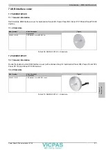
Page 277: ...r data Model number Short description Figure Accessories 5AC900 1201 00 USB interface cover M20 IP65 flat Table 209 5AC900 1201 00 Order data 7 2 5AC900 1201 01 7 2 1 General information Round front s...

Page 278: ...Short description Figure Accessories 5AC900 BLOC 00 Terminal block with brackets 10 pcs replacement part Table 211 5AC900 BLOC 00 Order data 8 2 5AC900 BLOC 01 8 2 1 General information These replace...

Page 279: ...9 Retaining clips 9 1 5AC900 CLIP 01 9 1 1 General information These replacement clips are used to mount B R panel devices 9 1 2 Order data Model number Short description Figure Accessories 5AC900 CL...

Page 280: ...e system The data specifications for the complete system take precedence over those of individual components Product ID 5AC804 MFLT 00 General information Certification CE Yes cULus Yes cULus HazLoc C...

Page 281: ...Figure 160 5AC804 MFLT 00 Drilling template 10 1 6 Connecting to the end device The line filter must be connected between the voltage supply and the end device The following points must be observed Us...

Page 282: ...tended functions from being triggered when handling the touch screen or pressing keys This device should be cleaned with a moist cloth The cloth should be moistened with water and detergent a screen c...

Page 283: ...arted and subsequently checked by the system every 24 hours During this measurement the battery is subjected to a brief load approximately 1 second and then evaluated Once determined the battery statu...

Page 284: ...inserting the battery Reconnect the power supply to the B R Industrial PC plug in the power cable Reset the date and time in BIOS Warning Lithium batteries are considered hazardous waste Used batteri...

Page 285: ...Maintenance and service Replacing a CompactFlash card Chapter 7 Maintenance and service Power Panel 500 user s manual V1 40 285 Ejector CompactFlash Figure 165 CompactFlash ejector...

Page 286: ...oring I O area power supply Key and LED handling coordination Advanced desktop operation keys USB forwarding Backlight control for the display Statistical data recording power cycles records every swi...

Page 287: ...Chemical resistance1 Acetone methylene chloride methyl ethyl ketone isopropyl alcohol hexane turpentine mineral spir its unleaded gasoline diesel motor oil gear lubricating oil antifreeze ammonia bas...

Page 288: ...e moistened with water and detergent a screen cleaning agent or alcohol ethanol The cleaning agent should be applied to the cloth beforehand not sprayed directly on the device Aggressive solvents chem...

Page 289: ...cetate Butylcellosolve Ether Acetone Methyl ethyl ketone Dioxan Cyclohexanone MIBK Isophorone Formic acid 50 Acetic acid 50 Phosphoric acid 30 Hydrochloric acid 36 Nitric acid 10 Trichloracetic acid 5...

Page 290: ...A Viewing angles 290 Power Panel 500 user s manual V1 40 4 Viewing angles Viewing angle specifications R L U D for the display types are listed in the technical data for each device R L U D Facing 6...

Page 291: ...s for the PP100 200 PP300 400 PP500 AP900 PPC700 and PPC800 are 0 5 mm The cutout tolerance values from the AP1000 are 0 mm 0 5 mm Compatibilities between device types is represented on each line by m...

Page 292: ...x 312 415 x 313 415 x 312 415 x 312 Outer dimensions 435 x 430 435 x 430 435 x 430 435 x 430 435 x 430 15 Vertical1 Installation dimensions 415 x 412 415 x 412 415 x 413 415 x 412 415 x 412 Outer dim...

Page 293: ...300 400 8 5 AP900 PPC700 PP500 Cutout for AP900 PPC700 PP500 device 4 5 423 x 288 10 10 8 5 Installation dimensions e g depends on device type Outer dimensions PP500 403 x 271 402 x 266 5 Figure 168 O...

Page 294: ...199 x 226 8 199 x 232 PP500 5 2 AP1000 6 5 PP500 AP1000 Figure 171 Mounting compatibility 5 7 device Vertical1 5 7 Automation Panel 1000 and Power Panel 500 devices are not 100 mounting compatible wit...

Page 295: ...400 AP900 PPC700 13 PP100 200 300 400 8 5 AP900 PPC700 PP500 AP1000 Cutout for AP900 PPC700 device 4 5 423 x 288 10 10 8 5 402 x 271 402 x 266 5 403 x 271 PP500 Cutout for PP500 AP1000 device AP1000 F...

Page 296: ...900 Panel PC 700 and Power Panel 500 devices are not 100 mounting compatible with Power Panel 100 200 300 400 devices in Vertical1 format Automation Panel 1000 Au tomation Panel 900 Panel PC 700 and P...

Page 297: ...PPC700 PP500 AP1000 Cutout for AP900 PPC700 PP500 AP1000 device 1 5 342 x 267 345 x 267 PP500 AP1000 Figure 175 Mounting compatibility 12 1 device Horizontal1 12 1 Automation Panel 1000 Automation Pan...

Page 298: ...n conditions When mounting make sure that the PP100 200 PP300 400 AP900 PPC700 and PPC800 devices are placed and mounted as close to the center of the cutout as possible Failure to do so can prevent t...

Page 299: ...e Horizontal1 17 Automation Panel 900 devices are 100 mounting compatible with Panel PC 700 devices in the Horizontal1 format 5 2 7 19 devices Cutout tolerance values for the PP100 200 PP300 400 PP500...

Page 300: ...Cutout tolerance values for the PP100 200 PP300 400 PP500 AP900 PPC700 and PPC800 are 0 5 mm The cutout tolerance values from the AP1000 are 0 mm 0 5 mm 583 x 464 8 5 8 5 8 5 8 5 Outer contour of devi...

Page 301: ...al or pin is not connected to a module ND Not defined In data tables this stands for a value that has not been defined This may be be cause a cable manufacturer does not provide certain technical data...

Page 302: ...ss a concrete application problem It sets up the system software and uses this for fulfilling individual tasks Application software can be accommodated in standard software used by a large number of c...

Page 303: ...nstallation 65 Figure 28 5PP520 1043 00 Temperature humidity diagram 66 Figure 29 5PP580 1043 00 Dimensions 70 Figure 30 5PP580 1043 00 Cutout installation 70 Figure 31 5PP580 1043 00 Temperature humi...

Page 304: ...58 Figure 86 US15W OEM Features Men 159 Figure 87 US15W OEM Features CPU Board Features 160 Figure 88 US15W OEM Features CPU Board Features LPC Devices 161 Figure 89 US15W OEM Features CPU Board Featu...

Page 305: ...ons 259 Figure 143 ATTO Disk Benchmark v2 34 read comparison 5CFCRD xxxx 04 and 5CFCRD xxxx 06 260 Figure 144 ATTO Disk Benchmark v2 34 write comparison 5CFCRD xxxx 04 and 5CFCRD xxxx 06 260 Figure 14...

Page 306: ...mpatibility 10 4 device Vertical1 296 Figure 175 Mounting compatibility 12 1 device Horizontal1 297 Figure 176 Mounting compatibility 15 device Horizontal1 298 Figure 177 Mounting compatibility 15 dev...

Page 307: ...52 0573 00 Technical data 53 Table 30 5PP520 0702 00 Order data 57 Table 31 5PP520 0702 00 Technical data 58 Table 32 5PP520 1043 00 Order data 62 Table 33 5PP520 1043 00 Technical data 63 Table 34 5P...

Page 308: ...Table 89 RS232 422 485 I O address and IRQ 123 Table 90 RS232 Bus length and transfer rate 124 Table 91 RS232 Cable requirements 124 Table 92 RS422 Bus length and transfer rate 124 Table 93 RS422 Cabl...

Page 309: ...ettings Configuration options 200 Table 140 US15W Power Platform power management Configuration options 201 Table 141 US15W Boot menu Configuration options 202 Table 142 US15W Boot Legacy Configuratio...

Page 310: ...06 5CFCRD 8192 06 5CFCRD 016G 06 5CFCRD 032G 06 Order data 254 Table 195 5CFCRD 0512 06 5CFCRD 1024 06 5CFCRD 2048 06 5CFCRD 4096 06 5CFCRD 8192 06 5CFCRD 016G 06 5CFCRD 032G 06 Technical data 255 Ta...

Page 311: ...Power Panel 500 user s manual V1 40 311 Table 218 Chemical resistance of the panel overlay 289 Table 219 Product abbreviations 291 Table 220 Device compatibilityoverview 291 Table 221 Abbreviations in...

Page 312: ...254 5CFCRD 1024 03 265 5CFCRD 1024 04 261 5CFCRD 1024 06 254 5CFCRD 2048 03 265 5CFCRD 2048 04 261 5CFCRD 2048 06 254 5CFCRD 4096 03 265 5CFCRD 4096 04 261 5CFCRD 4096 06 254 5CFCRD 8192 03 265 5CFCRD...

Page 313: ...P5IO GNAC 00 121 5SWLIN 0136 MUL 232 5SWUTI 0001 000 243 5SWWCE 0836 ENG 228 5SWWI7 0100 ENG 221 5SWWI7 0100 GER 221 5SWWI7 0300 MUL 221 5SWWI7 0536 ENG 225 5SWWI7 0736 MUL 225 5SWWI7 1100 ENG 221 5SW...

Page 314: ...t 154 backup BIOS 159 barcode 27 Battery 32 BIOS ACPI table features control 187 Advanced 177 Advanced CPU control 198 Boot 202 Boot configuration 179 Boot type order 204 Channel 1 master 182 Channel...

Page 315: ...ting switch 116 120 CE mark 244 Certifications 245 Germanischer Lloyd 245 certifications GOST R 245 Certifications UL 245 Chemical resistance 289 Clamping blocks 278 Cleaning 282 287 climate controlle...

Page 316: ...luating the battery status 32 283 example programs 142 F female Smart Display Link DVI connector 121 Firmware upgrade 218 Flex radius 143 Flex radius specifications 143 Free space 138 front USB 31 Fun...

Page 317: ...116 118 120 Line filter 280 Linux 232 loopback plug 141 Low voltage directive 244 M Main memory 104 Manual history 10 MIC Line IN Line OUT 107 126 Mode Node switches 34 Mounting compatibility 291 Moun...

Page 318: ...distribution I O address assignment 214 Retaining clips 279 revision 27 RS232 Bus length 124 Cable type 124 RS422 Bus length 124 Cable type 124 RS485 Bus length 125 Cable type 125 RS485 interface 124...

Page 319: ...139 Temperature testing procedure 139 terminating resistor 116 120 tolerance 291 293 295 297 298 299 299 300 Touch screen calibration 153 U UL certification 245 Upgrade BIOS 216 Firmware 218 Upgrade...

Reviews: