Technical data • Complete system
Chapter 2
Technical data
Automation Panel 9x3 User's Manual V1.00
27
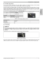
2.5.2 +24 VDC supply voltage
The 3-pin male connector required for the supply voltage connection is not included in delivery. It can be ordered
from B&R using model number 0TB103.9 (screw clamp) or 0TB103.91 (cage clamp).
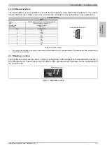
The pinout is listed in the following table. The supply voltage is protected internally by a soldered fuse (15 A, fast-
acting) to prevent damage to the device in the event of an overload (fuse replacement necessary) or if the voltage
supply is connected incorrectly (reverse polarity protection - fuse replacement not necessary). The device must be
returned to B&R for repairs if the fuse is blown in the event of an error.
+24 VDC supply voltage
Protected against reverse polarity
Pin
Description
1
+
2
Functional ground
3
-
Model number
Short description
Terminal blocks
0TB103.9
Connector 24 V 5.08 3-pin screw clamp
0TB103.91
Connector 24 V 5.08 3-pin cage clamp
3-pin female connector
+24 VDC supply voltage
Table 21: +24 VDC supply voltage connection
Electrical characteristics
Nominal voltage
24 VDC ±25%
Nominal current
Max. 2.5 A
Electrical isolation
Yes
Uninterruptible power supply
No
2.5.2.1 Grounding
Caution!
The functional ground (pin 2) must be connected to ground (e.g. control cabinet) using the shortest
possible path. Using the largest possible conductor cross section on the supply connector is recom-
mended.
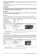
The ground connection is located beside the power supply for the link modules.
Grounding
Figure 10: Ground connection
The ground connection can be used, for example, to fasten a copper strip to a central grounding point in the control
cabinet or system where the device is installed. The largest possible conductor cross section should be used.


