Technical data • Introduction
12
Automation Panel 9x3 User's Manual V1.00
Chapter 2 • Technical data
1 Introduction
1.1 About this user's manual
This user's manual contains all relevant information about a functioning Automation Panel 9x3 rack-mounted de-
vice.
This user's manual applies to the modular Automation Panel 9x3 product generations. Information about Automa-
tion Panel 920, 980, 981 and 982 systems can be found in the Automation Panel 900 user's manual.
1.2 Description of individual modules
1.2.1 Display units
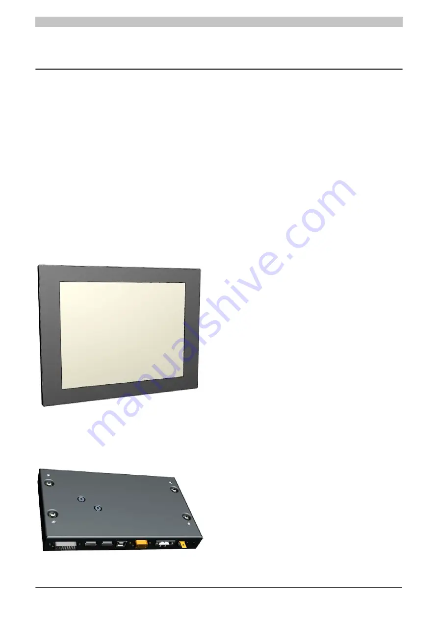
Display units consist of a display and touch screen and form the basis for each Automation Panel 9x3 and Panel
PC 900 System. Different display sizes and touch screen technologies are available. These display units can be
operated exclusively as a complete system together with a link module (Automation Panel 9x3) or CPU board and
system unit (Panel PC 900).
Model numbers for display units with single-touch technology begin with 5AP923.xxxx-xx; those for display units
with multi-touch technology begin with 5AP933.xxxx-xx.
1.2.2 Link modules
Link modules have various graphics interfaces and connections. A functioning Automation Panel 9x3 is put together
by installing a link module in a display unit. Automation Panel 9x3 systems are mounted using retaining clips.
A link module cannot function without a display unit.


