background image

Technical data  • Individual components

158

Automation PC 810 with GM45 CPU board user's manual V1.28

3.7.4 5PC810.FA05-00

3.7.4.1 General information

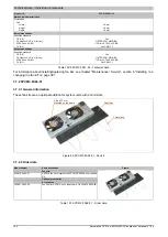
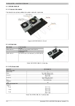
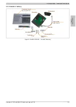
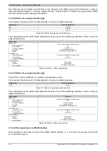
This fan kit is an optional addition for system units with 5 card slots.

Dust filter

Filter clasp

3 fan ø 70 mm

Mounted on the frame

Figure 67: 5PC810.FA05-00 - Fan kit

3.7.4.2 Order data

Model number

Short description

Figure

Fan kits

5PC810.FA05-00

APC810 fan kit for system unit 5PC810.SX05-00.

Optional accessories
Accessories

5AC801.FA05-00

Fan filter for APC810 5 pcs. (spare part), for 5PC810.SX05-00.

Table 105: 5PC810.FA05-00 - Order data

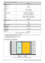
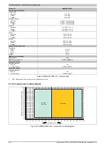
3.7.4.3 Technical data

Product ID

5PC810.FA05-00

General information

Number of fans

3

Speed

Max. 4300 rpm ±10%

Noise level

32 dB

Service life

60000 hours at 40 °C

Type

Double ball bearings

Certification

CE

Yes

Mechanical characteristics

Dimensions

Fan

Width

70 mm

Height

70 mm

Depth

15 mm

Recommendations

Specified standard

CE (CE)

Yes

Recommendations

Specified standard

CE (CE)

Yes

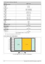
Table 106: 5PC810.FA05-00 - Technical data

For information about installing/replacing fan kits, see chapter "Maintenance / Service", section 6 "Installing / ex-

changing the fan kit" on page 381.

Summary of Contents for Automation PC 810

Page 1: ...rate as of the date of publication however Bernecker Rainer Industrie Elektronik Ges m b H makes no warranty ex pressed or implied with regard to the products or documentation contained within this ma...

Page 2: ...Chapter 1 General information Chapter 2 Technical data Chapter 3 Commissioning Chapter 4 Software Chapter 5 Standards and certifications Chapter 6 Accessories Chapter 7 Maintenance Service Appendix A...

Page 3: ...3 Temperature monitoring 28 2 1 4 Temperature sensor locations 28 2 2 Humidity specifications 29 2 3 Power management 30 2 3 1 Supply voltage block diagram 30 2 3 2 Power calculation with 5PC810 SX01...

Page 4: ...810 SX02 00 72 3 1 3 5PC810 SX03 00 79 3 1 4 5PC810 SX05 00 86 3 2 Bus units 93 3 2 1 General information 93 3 2 2 Order data 94 3 2 3 Technical data 94 3 3 CPU boards GM45 96 3 3 1 General informatio...

Page 5: ...nding concept 174 4 General instructions for performing Temperature tests 175 4 1 Procedure 175 4 2 Evaluation of temperatures in Windows operating systems 175 4 2 1 Evaluation using B R Control Cente...

Page 6: ...irements 195 5 10 2 Link modules 195 5 10 3 Cables 196 5 10 4 BIOS settings 197 5 11 Six AP900 and two AP800 units via onboard SDL and SDL AP Link 198 5 11 1 Basic system requirements 198 5 11 2 Link...

Page 7: ...1 2 I O address assignments 250 1 11 3 Interrupt assignments in PIC mode 251 1 11 4 Interrupt assignments in APIC mode 252 2 Upgrade information 255 2 1 BIOS upgrade 255 2 1 1 Important information 25...

Page 8: ...Runtime 274 8 1 General information 274 8 2 Order data 274 8 3 Automation Runtime Windows ARwin 274 8 4 Automation Runtime Embedded ARemb 274 9 B R Automation Device Interface ADI Control Center 275...

Page 9: ...cards 299 5 1 General information 299 5 2 General information 299 5 2 1 Flash technology 299 5 2 2 Wear leveling 299 5 2 3 ECC error correction 299 5 2 4 S M A R T support 299 5 2 5 Maximum reliabilit...

Page 10: ...General information 327 7 1 2 Order data 327 7 1 3 Technical data 327 7 1 4 Temperature humidity diagram 328 7 2 5MMUSB 2048 01 329 7 2 1 General information 329 7 2 2 Order data 329 7 2 3 Technical...

Page 11: ...mensions 346 11 2 5ACPCI ETH3 01 347 11 2 1 General information 347 11 2 2 Order data 347 11 2 3 Technical data 347 11 2 4 Driver support 348 11 2 5 Dimensions 349 12 Cables 350 12 1 DVI cables 350 12...

Page 12: ...on with installed add on interface module 389 7 2 1 APC810 1 card slot 389 7 2 2 APC810 2 and 3 card slot 391 7 2 3 APC810 5 card slot 393 8 Installing the UPS fuse kit on the battery unit 395 8 1 Pro...

Page 13: ...components on page 25 5AC801 HDDI 03 5ACPCI RAIC 05 and 5MMHDD 0250 00 updated in section 2 1 1 Maximum ambient temperature with fan kit on page 27 and 2 2 Humidity specifications on page 29 1 12 18 F...

Page 14: ...nd 5AC801 SSDI 02 on page 117 added Section General instructions for performing Temperature tests on page 175 updated Windows 7 Service Pack 1 updated see Windows 7 on page 268 Windows Embedded Standa...

Page 15: ...uidelines for proper ESD handling Electrical components with a housing Do not touch the connector contacts on connected cables Do not touch the contact tips on circuit boards Electrical components wit...

Page 16: ...lers operating monitoring devices or uninterruptible power supplies it is necessary for certain parts to carry dangerous voltage levels over 42 VDC Touching one of these parts can result in a life thr...

Page 17: ...t 2 7 1 Separation of materials It is necessary to separate different materials so the device can undergo an environmentally friendly recycling process Component Disposal Programmable logic controller...

Page 18: ...o equipment Caution Disregarding these safety guidelines and notices can result in injury or damage to equipment Information This information is important for preventing errors Table 3 Description of...

Page 19: ...5 01 APC810 bus 2 PCI 3 PCI Express x1 94 5PC810 BX05 02 APC810 bus 5 PCI 94 CPU boards 5PC800 BM45 00 Intel Core2 Duo T9400 CPU board 2 53 GHz dual core 1066 MHz FSB 6 MB L2 cache chipset GM45 2 sock...

Page 20: ...r system unit 5PC810 SX01 00 153 5PC810 FA02 01 APC810 fan kit for system unit 5PC810 SX02 00 from revision D0 154 5PC810 FA03 00 APC810 fan kit for system unit 5PC810 SX03 00 156 5PC810 FA05 00 APC81...

Page 21: ...PPC800 for system units 5PC600 SX01 00 from Rev H0 5PC600 SX02 00 from Rev G0 5PC600 SX02 01 from Rev H0 5PC600 SX05 00 from Rev F0 5PC600 SX05 01 from Rev F0 5PC600 SF03 00 from Rev A0 5PC810 SX 5PC...

Page 22: ...rol cabinet Drive inserts DVD HDD and two CompactFlash slots are pro tected behind a cover on the front of the device only one CF slot can be used with the GM45 CPU board Modular plug in technology ma...

Page 23: ...to connect various display devices to the Monitor Panel video output supports RGB DVI and SDL Smart Display Link signals 2nd graphics line by installing the optional AP Link card Easy slide in drive...

Page 24: ...PC800 BM45 01 5PC810 BX03 00 2 PCI 1 PCIe Fan kit 5PC810 FA01 00 5PC810 FA02 01 5PC810 FA05 00 5PC810 FA03 00 Select 1 5PC810 BX01 01 1 PCIe 5PC810 BX02 01 1 PCI 1 PCIe 5PC810 BX05 01 2 PCI 3 PCIe 5PC...

Page 25: ...module battery Select one Terminal blocks 0TB103 9 screw clamps 0TB103 91 cage clamps Select one Software CompactFlash Select one 5CFCRD 0512 06 5CFCRD 1024 06 5CFCRD 2048 06 5CFCRD 4096 06 5CFCRD 81...

Page 26: ...ons Experience has shown that higher ambient temperatures can be reached in typical applications e g those in Microsoft Windows Testing and evaluation must be performed on site by the user temperature...

Page 27: ...03 00 80 System units 5PC810 SX05 00 80 Power supply 5AC600 CANI 00 5AC600 485I 00 5AC801 SDL0 00 5AC801 RDYR 00 5ACPCI RAIC 03 24 hours standard 5ACPCI RAIC 05 24 hours standard 50 Additional insert...

Page 28: ...e in drive etc The temperatures2 can be read in BIOS Advanced CPU monitor or in Microsoft Windows operating systems via the B R Control Center3 For applications that don t use Windows the temperatures...

Page 29: ...90 5AC801 DVDS 00 8 to 90 5 to 95 Slide in drives 5AC801 DVRS 00 8 to 90 5 to 95 5AC600 CANI 00 5 to 90 5 to 95 5AC600 485I 00 5 to 90 5 to 95 5AC801 SDL0 00 5 to 90 5 to 95 5AC801 RDYR 00 5 to 90 5 t...

Page 30: ...UPS add on module optional 12 V PCI bus Figure 4 Supply voltage for system units Description 15 V is generated from the supply voltage using a DC to DC converter This electrically isolated 15 V suppl...

Page 31: ...x4 Karte optional max 20 W1 12 V Verbraucher 12 V maximal m glich bei 5 V 65 Systemeinheit Fixverbraucher 4 4 Hard Disk Slide in compact 4 4 Slide in Laufwerk Hard Disk DVD ROM 4 4 USB Peripherie USB2...

Page 32: ...onal max 20 W1 12 V Verbraucher 12 V maximal m glich bei 5 V 65 Systemeinheit Fixverbraucher 4 4 Hard Disk Slide in compact 4 4 Slide in Laufwerk Hard Disk DVD ROM 4 4 USB Peripherie USB2 und USB4 je...

Page 33: ...raucher 12 V maximal m glich bei 5 V 65 Systemeinheit Fixverbraucher 4 4 Hard Disk Slide in compact 4 4 Slide in Laufwerk Hard Disk DVD ROM 4 4 USB Peripherie USB2 und USB4 je 2 5 W USB Peripherie USB...

Page 34: ...maximal m glich bei 5 V 65 Systemeinheit Fixverbraucher 4 4 Hard Disk Slide in compact 4 4 Slide in Laufwerk Hard Disk DVD ROM 4 4 USB Peripherie USB2 und USB4 je 2 5 W USB Peripherie USB1 USB3 und US...

Page 35: ...r 12 V maximal m glich bei 5 V 65 Systemeinheit Fixverbraucher 4 4 Hard Disk Slide in compact 4 4 Slide in Laufwerk Hard Disk DVD ROM 4 4 USB Peripherie USB2 und USB4 je 2 5 W USB Peripherie USB1 USB3...

Page 36: ...l m glich bei 5 V 65 Systemeinheit Fixverbraucher 4 4 Hard Disk Slide in compact 4 4 Slide in Laufwerk Hard Disk DVD ROM 4 4 USB Peripherie USB2 und USB4 je 2 5 W USB Peripherie USB1 USB3 und USB5 je...

Page 37: ...sents all of the individual components built into the system model number name revision serial number delivery date and duration of warranty For configuration details go to www br automation com and e...

Page 38: ...sembled device in the search field after selecting the Serial number option tab at the top of the homepage www br automation com The search provides a detailed list of the installed components List of...

Page 39: ...sk Battery 950 mAh V battery Line driver RS232 Line driver RS232 SM bus BIOS Flash Buffering 10 ms Voltage supply 3 pin DC DC Isolated DC DC Switching DC DC Switching 5 volts 3 3 volts 15 6 volts Rese...

Page 40: ...ring 10 ms Voltage supply 3 pin DC DC Isolated DC DC Switching DC DC Switching 5 volts 3 3 volts 15 6 volts Reset button Optional Fan 1 Optional Fan 2 Optional Fan 3 IF option CAN or RS485 Analog RGB...

Page 41: ...Switching DC DC Switching 5 volts 3 3 volts 15 6 volts Reset button Optional Fan 1 Optional Fan 2 Optional Fan 3 IF option CAN or RS485 Analog RGB SDL IF SDVO B DMI Interface SM bus SATA 0 TMDS Sil 1...

Page 42: ...Switching 5 volts 3 3 volts 15 6 volts Reset button Optional Fan 1 Optional Fan 2 Optional Fan 3 IF option CAN or RS485 Analog RGB SDL IF SDVO B DMI Interface SM bus SATA 0 TMDS Sil 1362A Battery Unit...

Page 43: ...C Switching 5 volts 3 3 volts 15 6 volts Reset button Optional Fan 1 Optional Fan 2 Optional Fan 3 IF option CAN or RS485 Analog RGB SDL IF SDVO B DMI Interface SM bus SATA 0 TMDS Sil 1362A Battery Un...

Page 44: ...nal Fan 1 Optional Fan 2 Optional Fan 3 IF option CAN or RS485 Analog RGB SDL IF SDVO B DMI Interface SM bus SATA 0 TMDS Sil 1362A Battery Unit 6 pin Position controller Temperature sensors Controller...

Page 45: ...button Optional Fan 1 Optional Fan 2 Optional Fan 3 IF option CAN or RS485 Analog RGB SDL IF SDVO B DMI Interface SM bus SATA 0 TMDS Sil 1362A Battery Unit 6 pin Position controller Temperature senso...

Page 46: ...Optional Fan 2 Optional Fan 3 IF option CAN or RS485 Analog RGB SDL IF SDVO B DMI Interface SM bus SATA 0 TMDS Sil 1362A Battery Unit 6 polig Position controller Temperature sensors Controller Add on...

Page 47: ...y The device must be returned to B R for repairs if the fuse is blown in the event of an error Supply voltage Protected against reverse polarity Pin Description 1 2 Functional ground 3 Model number Sh...

Page 48: ...n the device or module have been numbered as such for easy identification This numbering may differ from that used by the particular operating system 2 6 3 Serial interface COM2 Serial interface COM21...

Page 49: ...11 12 22 23 24 21 17 18 19 20 c1 c4 c2 c3 c5 Table 18 Pinout DVI connection 1 Protected internally by a multifuse 2 6 4 2 Cable lengths and resolutions for SDL transmission The following table lists...

Page 50: ...imum resolution depending on the DVI cable being used Resolution DVI cables Segment length m VGA 640 x 480 SVGA 800 x 600 XGA 1024 x 768 SXGA 1280 x 1024 UXGA 1600 x 1200 FHD 1920 x 1080 1 8 5CADVI 00...

Page 51: ...blinking da ta transfer in progress 1 Speed LED Link LED Table 21 Ethernet connection ETH1 1 The interfaces etc available on the device or module have been numbered as such for easy identification Thi...

Page 52: ...ta transfer in progress 1 Speed LED Link LED Table 22 Ethernet connection ETH2 1 The interfaces etc available on the device or module have been numbered as such for easy identification This numbering...

Page 53: ...pe USB 2 0 Design Type A Transfer rate Low speed 1 5 Mbit s full speed 12 Mbit s high speed 480 Mbit s Current load2 USB1 USB3 USB2 USB4 Max 1 A Max 500 mA Cable length Max 5 m without hub 4 x USB typ...

Page 54: ...connections are not supported MIC Line IN Line OUT 3 5mm socket female Table 25 MIC Line IN Line OUT 2 6 9 Add on interface slot An optional add on interface e g CAN RS485 can be installed here See al...

Page 55: ...on UPS module 5AC600 UPSB 00 Battery unit 5 Ah 5CAUPS 0005 00 UPS cable 0 5 m 5CAUPS 0030 00 UPS cable 3 m APC810 Ready relay 5AC801 RDYR 01 APC810 Ready relay 2 1 2 3 4 5 6 Table 27 Add on UPS slot...

Page 56: ...ted in every system unit or card slot The following table provides an overview of the slots where 64 bit cards can be inserted Card slot 1 Card slot 2 Card slot 3 Card slot 4 Card slot 5 System unit B...

Page 57: ...tomation PC 810 with GM45 CPU board user s manual V1 28 57 Card slot 1 Card slot 2 Card slot 3 Card slot 4 Card slot 5 Card slot 1 Card slot 2 Card slot 1 Card slot 1 Card slot 2 Card slot 3 5PC810 SX...

Page 58: ...the display unit Table 29 Status LEDs Data 1 Only lit when an add on UPS module is installed The light for the Status LEDs is fed to the front cover via fiber optic lines Figure 18 Status LEDs on the...

Page 59: ...out shutting down the APC810 data could be lost Pressing the power button does not reset the MTCX processor Table 31 Power button 2 6 16 Reset button Information From MTCX PX32 firmware V00 11 and hig...

Page 60: ...lied components and a self discharge of 40 Battery status evaluation The status of the battery is determined immediately after the device is started and subsequently checked by the system every 24 hou...

Page 61: ...Key Dongle B R recommends a hardware security key dongle based on the DS1425 from MAXIM previously Dallas Semi conductors for software copy protection Hardware Security Key A hardware security key don...

Page 62: ...lash 4096 MB B R 5CFCRD 8192 06 CompactFlash 8192 MB B R 5CFCRD 016G 06 CompactFlash 16 GB B R 5CFCRD 032G 06 CompactFlash 32 GB B R 5CFCRD 0064 03 CompactFlash 64 MB WD 5CFCRD 0128 03 CompactFlash 12...

Page 63: ...s capability it must be supported by the operating system 2 6 22 Slide in slot 2 The internal connection between slide in slot 2 and the chipset is made via a PCIe to SATA Bridge SiL 3531 and USB Slid...

Page 64: ...k Note Please see the manual for information about using this hard disk 5AC801 HDDI 04 500 GB SATA hard disk slide in compact 24 7 hard disk Note Please see the manual for information about using this...

Page 65: ...sockets for SO DIMM DDR3 modules Terminal blocks 0TB103 9 24 VDC supply voltage plug 3 pin female 3 31 mm screw clamp protected against vibration by the screw flange 0TB103 91 24 VDC supply voltage pl...

Page 66: ...5PC820 1505 00 5PC820 1906 00 Order cable 5CAUPS 0005 00 or 5CAUPS 0030 00 and battery unit 5AC600 UPSB 00 separately Accessories 5ACPCI ETH1 01 PCI Ethernet card 1x 10 100 5ACPCI ETH3 01 PCI Ethernet...

Page 67: ...Product ID 5PC810 SX01 00 General information Dongle port Yes Cooling Passive via heat sink and optionally supported with an active fan kit 1 LEDs Power HDD Link 1 Link 2 B R ID code A3ED Battery Type...

Page 68: ...10 100 1000 Mbit s Max baud rate 1 Gbit s Panel Monitor interface Design DVI I socket Type SDL DVI Monitor CAN Note Optional Audio Type AC97 sound 4 Inputs Microphone Line in Outputs Line OUT Add on i...

Page 69: ...14F2 BR UL HazLoc Cl I Div 2 cULus LISTED 2P61 ABCD BR ATEX Zone 22 EX II 3D tc IIIA T85 0 55 C BR GL GL Cat C EMC 1 Recommendations Specified standard CE CE Yes UL 508 cULus LISTED 14F2 BR UL HazLoc...

Page 70: ...V1 28 3 1 1 5 Dimensions 71 18 35 9 42 7 184 6 244 18 3 65 5 A 252 7 241 71 2 5 24 270 222 15 5 260 13 5 4 11 5AC801 HS00 00 Measurement A depends on which heat sink is used 5AC801 HS00 01 Informatio...

Page 71: ...Technical data Automation PC 810 with GM45 CPU board user s manual V1 28 71 3 1 1 6 Drilling template 53 262 General tolerance according to ISO 2768 medium 0 0 18 71 18 270 Mounting plate outline APC...

Page 72: ...2048 MB PC3 8500 5MMDDR 4096 02 SO DIMM DDR3 RAM 4096 MB PC3 8500 Heat sink 5AC801 HS00 01 APC810 heat sink for CPU boards with dual core processors T7400 T9400 and P8400 Fan kit 5PC810 FA02 01 APC81...

Page 73: ...00 5PC820 1906 00 Order cable 5CAUPS 0005 00 or 5CAUPS 0030 00 and battery unit 5AC600 UPSB 00 separately Accessories 5ACPCI ETH1 01 PCI Ethernet card 1x 10 100 5ACPCI ETH3 01 PCI Ethernet card 3x 10...

Page 74: ...ta Product ID 5PC810 SX02 00 General information Dongle port Yes Cooling Passive via heat sink and optionally supported with an active fan kit 1 LEDs Power HDD Link 1 Link 2 B R ID code A3C7 Battery T...

Page 75: ...r rate 10 100 1000 Mbit s Max baud rate 1 Gbit s Panel Monitor interface Design DVI I socket Type SDL DVI Monitor CAN Note Optional Audio Type AC97 sound 4 Inputs Microphone Line in Outputs Line OUT A...

Page 76: ...azLoc Cl I Div 2 cULus LISTED 2P61 ABCD BR ATEX Zone 22 EX II 3D tc IIIA T85 0 55 C BR GL GL Cat C EMC 1 Recommendations Specified standard CE CE Yes UL 508 cULus LISTED 14F2 BR UL HazLoc Cl I Div 2 c...

Page 77: ...ual V1 28 77 3 1 2 5 Dimensions 110 5 70 5 4 20 3 42 7 9 11 244 18 3 105 A 241 110 5 254 6 245 15 270 222 24 2 5 15 260 5 19 184 6 5AC801 HS00 00 Measurement A depends on which heat sink is used 5AC80...

Page 78: ...78 Automation PC 810 with GM45 CPU board user s manual V1 28 3 1 2 6 Drilling template 90 3 262 General tolerance according to ISO 2768 medium 0 0 20 3 110 5 18 270 Mounting plate outline APC810 Figur...

Page 79: ...DR3 RAM 2048 MB PC3 8500 5MMDDR 4096 02 SO DIMM DDR3 RAM 4096 MB PC3 8500 Heat sink 5AC801 HS00 01 APC810 heat sink for CPU boards with dual core processors T7400 T9400 and P8400 Fan kit 5PC810 FA03 0...

Page 80: ...5CAUPS 0005 00 or 5CAUPS 0030 00 and battery unit 5AC600 UPSB 00 separately Accessories 5ACPCI ETH1 01 PCI Ethernet card 1x 10 100 5ACPCI ETH3 01 PCI Ethernet card 3x 10 100 Table 45 5PC810 SX03 00 Or...

Page 81: ...0 General information Dongle port Yes Cooling Passive via heat sink and optionally supported with an active fan kit 1 LEDs Power HDD Link 1 Link 2 B R ID code B2C3 Battery Type Renata 950 mAh Service...

Page 82: ...itor CAN Note Optional Audio Type AC97 sound 4 Inputs Microphone Line in Outputs Line OUT Add on interface slot Quantity 1 Inserts PCI PCIe slots Quantity 2 PCI and 1 PCIe slot 5 Slide in drives 1 Sli...

Page 83: ...x 3200 g component dependent Recommendations Specified standard CE CE Yes UL 508 cULus LISTED 14F2 BR Recommendations Specified standard CE CE Yes UL 508 cULus LISTED 14F2 BR Table 46 5PC810 SX03 00 T...

Page 84: ...V1 28 3 1 3 5 Dimensions 5AC801 HS00 00 Measurement A depends on which heat sink is used 5AC801 HS00 01 Information Entry in mm Model number 5AC801 HS00 02 12 8 28 12 8 30 5 70 131 5 4 11 9 42 7 185 1...

Page 85: ...chnical data Automation PC 810 with GM45 CPU board user s manual V1 28 85 3 1 3 6 Drilling template 100 5 262 General tolerance according to ISO 2768 medium 0 0 30 5 131 270 18 Mounting plate outline...

Page 86: ...for GM45 CPU boards 5MMDDR 2048 02 SO DIMM DDR3 RAM 2048 MB PC3 8500 5MMDDR 4096 02 SO DIMM DDR3 RAM 4096 MB PC3 8500 Heat sink 5AC801 HS00 01 APC810 heat sink for CPU boards with dual core processors...

Page 87: ...UPS 0030 00 and battery unit 5AC600 UPSB 00 separately Accessories 5ACPCI ETH1 01 PCI Ethernet card 1x 10 100 5ACPCI ETH3 01 PCI Ethernet card 3x 10 100 Table 47 5PC810 SX05 00 Order data 3 1 4 3 Inte...

Page 88: ...Cooling Passive via heat sink and optionally supported with an active fan kit 1 LEDs Power HDD Link 1 Link 2 B R ID code A3EE Battery Type Renata 950 mAh Service life 2 years 2 Removable Yes accessib...

Page 89: ...puts Microphone Line in Outputs Line OUT Add on interface slot Quantity 1 Inserts PCI PCIe slots Quantity 4 PCI and 1 PCIe slots or 2 PCI and 3 PCIe slots or 5 PCI slots 5 Slide in drives 2 Slide in c...

Page 90: ...ations Specified standard CE CE Yes UL 508 cULus LISTED 14F2 BR Recommendations Specified standard CE CE Yes UL 508 cULus LISTED 14F2 BR Table 48 5PC810 SX05 00 Technical data 1 A fan kit is absolutel...

Page 91: ...al V1 28 91 3 1 4 5 Dimensions 3 18 244 25 7 70 70 5 4 9 11 15 24 270 24 2 5 222 191 4 184 6 42 7 254 5 191 4 5 260 15 241 185 9 A 5AC801 HS00 00 Measurement A depends on which heat sink is used 5AC80...

Page 92: ...Automation PC 810 with GM45 CPU board user s manual V1 28 3 1 4 6 Drilling template 165 7 262 General tolerance according to ISO 2768 medium 0 0 25 7 191 4 18 270 Mounting plate outline APC810 95 7 Fi...

Page 93: ...he bus units are compatible with the system units in 1 2 3 or 5 card slot sizes available with PCI and or PCI Express support 1 PCI slot 5PC810 BX01 00 5PC810 BX01 01 1 PCIe slot Figure 35 1 slot bus...

Page 94: ...X05 02 APC810 bus 5 PCI Table 49 5PC810 BX01 00 5PC810 BX01 01 5PC810 BX02 00 5PC810 BX02 01 5PC810 BX03 00 5PC810 BX05 00 5PC810 BX05 01 5PC810 BX05 02 Order data 3 2 3 Technical data Product ID 5PC8...

Page 95: ...cified standard CE CE Yes UL HazLoc Cl I Div 2 cULus LISTED 2P61 ABCD BR LISTED 2P61 ABCD BR ATEX Zone 22 EX II 3D tc IIIA T85 0 55 C BR II 3D tc IIIA T85 0 55 C BR GL GL Cat C EMC 1 Cat C EMC 1 Cat C...

Page 96: ...2048 02 SO DIMM DDR3 RAM 2048 MB PC3 8500 5MMDDR 4096 02 SO DIMM DDR3 RAM 4096 MByte PC3 8500 Table 51 5PC800 BM45 00 5PC800 BM45 01 Order data 3 3 3 Technical data Product ID 5PC800 BM45 00 5PC800 B...

Page 97: ...ard CE CE Yes UL 508 cULus LISTED 14F2 BR UL HazLoc Cl I Div 2 cULus LISTED 2P61 ABCD BR ATEX Zone 22 EX II 3D tc IIIA T85 0 55 C BR Recommendations Specified standard CE CE Yes UL 508 cULus LISTED 14...

Page 98: ...ache GM45 chipset 2 sockets for SO DIMM DDR3 modules 5PC800 BM45 01 Intel Core2 Duo P8400 CPU board 2 26 GHz dual core 1066 MHz FSB 3 MB L2 cache GM45 chipset 2 sockets for SO DIMM DDR3 modules Table...

Page 99: ...ption Figure Main memory for GM45 CPU boards 5MMDDR 2048 02 SO DIMM DDR3 RAM 2048 MB PC3 8500 5MMDDR 4096 02 SO DIMM DDR3 RAM 4096 MByte PC3 8500 Table 55 5MMDDR 2048 02 5MMDDR 4096 02 Order data 3 5...

Page 100: ...sk Table 57 5AC801 HDDI 00 Order data 3 6 1 3 Technical data Information The following characteristics features and limit values only apply to this individual component and can deviate from those spec...

Page 101: ...duration no unrecoverable errors 400 g and 0 5 ms duration no unrecoverable errors Altitude Operation 300 to 5000 m Storage 300 to 12192 m Mechanical characteristics Installation Fixed 6 Dimensions Wi...

Page 102: ...ts 102 Automation PC 810 with GM45 CPU board user s manual V1 28 3 6 1 4 Temperature humidity diagram Temperature C Relative humidity RH non condensing Operation Storage Transport Figure 39 5AC801 HDD...

Page 103: ...ical data Information The following characteristics features and limit values only apply to this individual component and can deviate from those specified for the entire device For the entire device i...

Page 104: ...ristics Installation Fixed 7 Dimensions Width 13 mm Height 98 mm Depth 105 mm Weight 135 g Manufacturer information Manufacturer Fujitsu Manufacturer product ID MHY2160BH ESW Recommendations Specified...

Page 105: ...a 3 6 3 3 Technical data Information The following characteristics features and limit values only apply to this individual component and can deviate from those specified for the entire device For the...

Page 106: ...ors Altitude Operation 300 to 3048 m Storage 300 to 12192 m Mechanical characteristics Installation Fixed 6 Dimensions Width 13 mm Height 98 mm Depth 105 mm Weight 134 g Manufacturer information Manuf...

Page 107: ...Technical data Automation PC 810 with GM45 CPU board user s manual V1 28 107 3 6 3 4 Temperature humidity diagram Temperature C Relative humidity RH non condensing Operation Storage Transport Figure...

Page 108: ...rd disk Table 63 5AC801 HDDI 04 Order data 3 6 4 3 Technical data Information The following characteristics features and limit values only apply to this accessory and can deviate from those specified...

Page 109: ...llation Fixed 6 Dimensions Width 13 mm Height 98 mm Depth 105 mm Weight 134 g Manufacturer information Manufacturer Western Digital Manufacturer product ID WD5000LUCT Recommendations Specified standar...

Page 110: ...a 3 6 5 3 Technical data Caution A sudden loss of power may result in data loss In very rare cases mass memory may also be damaged To prevent damage and loss of data the use of a UPS device is recomme...

Page 111: ...ng Storage 5 to 95 non condensing Transport 5 to 95 non condensing Vibration Operation 7 to 800 Hz 2 17 g Storage 10 to 500 Hz 3 13 g Transport 10 to 500 Hz 3 13 g Shock Operation 1000 g 0 5 ms Storag...

Page 112: ...s 112 Automation PC 810 with GM45 CPU board user s manual V1 28 3 6 5 4 Temperature humidity diagram 0 Temperature C Relative humidity RH non condensing Operation Storage Transport Figure 43 5AC801 SS...

Page 113: ...801 HDDI 00 for cyclic reading and writing 20 40 60 80 100 120 140 160 0 5 1 2 4 8 16 32 128 64 256 512 1024 2048 4096 8192 Transfer rate MB s Transfer size kB 5AC801 HDDI 00 5AC801 SSDI 00 Figure 44...

Page 114: ...e see manual for proper use of the SSD Table 67 5AC801 SSDI 01 Order data 3 6 6 3 Technical data Caution A sudden loss of power may result in data loss In very rare cases mass memory may also be damag...

Page 115: ...Vibration Operation 5 to 700 Hz 2 17 g Storage 5 to 800 Hz 3 13 g Transport 5 to 800 Hz 3 13 g Shock Operation 1500 g 0 5 ms Storage 1500 g 0 5 ms Transport 1500 g 0 5 ms Altitude Operation 300 to 12...

Page 116: ...s 116 Automation PC 810 with GM45 CPU board user s manual V1 28 3 6 6 4 Temperature humidity diagram 0 Temperature C Relative humidity RH non condensing Operation Storage Transport Figure 46 5AC801 SS...

Page 117: ...Remark Please see manual for proper use of the SSD Table 69 5AC801 SSDI 02 Order data 3 6 7 3 Technical data Caution A sudden loss of power may result in data loss In very rare cases mass memory may...

Page 118: ...eration 5 to 700 Hz 2 17 g Storage 5 to 800 Hz 3 13 g Transport 5 to 800 Hz 3 13 g Shock Operation 1500 g 0 5 ms Storage 1500 g 0 5 ms Transport 1500 g 0 5 ms Altitude Operation 300 to 12 192 m Storag...

Page 119: ...Technical data Automation PC 810 with GM45 CPU board user s manual V1 28 119 3 6 7 4 Temperature humidity diagram 0 Temperature C Relative humidity RH non condensing Operation Storage Transport Figure...

Page 120: ...IO GMAC 00 Hinweis Beachten Sie das Manual zum Einsatz der SSD Table 71 5AC801 SSDI 03 Order data 3 6 8 3 Technical data Caution A sudden loss of power may result in data loss In very rare cases mass...

Page 121: ...g 0 5 ms Storage 1500 g 0 5 ms Transport 1500 g 0 5 ms Altitude Operation 300 to 12 192 m Storage 300 to 12 192 m Transport 300 to 12 192 m Mechanical characteristics Installation Fixed 2 Dimensions W...

Page 122: ...ot 1 for mechanical reasons closing the front door 3 6 9 2 Order data Model number Short description Figure Drives 5AC801 ADAS 00 SATA hard disk adapter to operate a slide in compact hard disk in a sl...

Page 123: ...lease see manual for proper use of the hard disk Table 75 5AC801 HDDS 00 Order data 3 6 10 3 Technical data Information The following characteristics features and limit values only apply to this indiv...

Page 124: ...recoverable errors 400 g and 0 5 ms duration no unrecoverable errors Altitude Operation 300 to 5000 m Storage 300 to 12192 m Mechanical characteristics Installation Fixed 6 Dimensions Width 22 mm Heig...

Page 125: ...Technical data Automation PC 810 with GM45 CPU board user s manual V1 28 125 3 6 10 4 Temperature humidity diagram Temperature C Relative humidity RH non condensing Operation Storage Transport Figure...

Page 126: ...entire device For the entire device in which this individual component is used refer to the data given specifically for the entire device Product ID 5AC801 DVDS 00 General information Certification C...

Page 127: ...and 11 ms duration Storage 60 g and 11 ms duration 200 g and 2 ms duration Transport 60 g and 11 ms duration 200 g and 2 ms duration Mechanical characteristics Dimensions Width 22 mm Height 172 5 mm D...

Page 128: ...s 128 Automation PC 810 with GM45 CPU board user s manual V1 28 3 6 11 5 Hot plug capable Hardware revision B0 of the slide in DVD ROM 5AC801 DVDS 00 does not offer SATA hot plug capability Other hard...

Page 129: ...features and limit values only apply to this individual component and can deviate from those specified for the entire device For the entire device in which this individual component is used refer to t...

Page 130: ...dity Operation 8 to 80 non condensing Storage 5 to 95 non condensing Transport 5 to 95 non condensing Vibration Operation 5 to 500 Hz 0 2g Storage 5 to 500 Hz 2g Transport 5 to 500 Hz 2g Shock Operati...

Page 131: ...Technical data Automation PC 810 with GM45 CPU board user s manual V1 28 131 3 6 12 4 Temperature humidity diagram Temperature C Relative humidity RH non condensing Operation Storage Transport Figure...

Page 132: ...Access LED yellow for primary HDD 0 and secondary hard disk HDD 1 Figure 52 PCI SATA RAID controller Information The PCI SATA RAID controller cannot be used in place of a Universal Power Supply UPS If...

Page 133: ...ax 84 6 Mbits s To From host Max 150 MB s Positioning time Minimum track to track 1 5 ms Nominal read only 12 ms Maximum read only 22 ms Electrical characteristics Power consumption 0 3A at 3 3V PCI b...

Page 134: ...ve humidity RH non condensing Operation Storage Transport Figure 53 5ACPCI RAIC 03 Temperature humidity diagram 3 6 13 5 Driver support Special drivers are necessary for operating the PCI SATA RAID co...

Page 135: ...rs 312 581 808 Bytes per sector 512 Cache 8 MB Speed 5400 rpm 1 Startup time Typ 4 s from 0 rpm to read access Service life 5 years S M A R T support Yes Access time 5 56 ms Supported transfer modes S...

Page 136: ...BH ESW Recommendations Specified standard CE CE Yes Recommendations Specified standard CE CE Yes Table 84 5ACPCI RAIC 04 Technical data 1 Temperature values for 305 meter altitude The temperature spec...

Page 137: ...primary HDD 0 and secondary hard disk HDD 1 Figure 55 PCI SATA RAID controller Information The PCI SATA RAID controller cannot be used in place of a Universal Power Supply UPS If the oper ating system...

Page 138: ...PCI bus 1A at 5V PCI bus Environmental conditions Temperature 1 Operation 2 0 to 60 C 24 hour operation 3 0 to 60 C Storage 40 to 70 C Transport 40 to 70 C Relative humidity 4 Operation 5 to 95 non c...

Page 139: ...condensing Operation Storage Transport Figure 56 5ACPCI RAIC 05 Temperature humidity diagram 3 6 15 5 Driver support Special drivers are necessary for operating the PCI SATA RAID controller Drivers fo...

Page 140: ...ary hard disk HDD 1 Figure 57 PCI SATA RAID controller Information The PCI SATA RAID controller cannot be used in place of a Universal Power Supply UPS If the oper ating system is shut down improperly...

Page 141: ...TA Access time 5 5 ms Supported transfer modes SATA II Data transfer rate Internal Max 147 MB s To From host Max 150 MB s SATA I max 300 MB s SATA II Positioning time Nominal read only 11 ms Maximum r...

Page 142: ...gram Temperature C Relative humidity RH non condensing Operation Storage Transport Figure 58 5ACPCI RAIC 06 Temperature humidity diagram 3 6 16 5 Driver support Special drivers are necessary for opera...

Page 143: ...is individual component and can deviate from those specified for the entire device For the entire device in which this individual component is used refer to the data given specifically for the entire...

Page 144: ...tion 300 to 3048 m Storage 300 to 12192 m Mechanical characteristics Dimensions Width 9 5 mm Height 69 mm Depth 100 mm Weight 100 g Manufacturer information Manufacturer Seagate Manufacturer product I...

Page 145: ...0 Order data 3 6 18 3 Technical data Information The following characteristics features and limit values only apply to this accessory and can deviate from those specified for the fully assembled devic...

Page 146: ...peration 305 to 3048 m Storage 305 to 12192 m Mechanical characteristics Dimensions Width 7 mm Height 69 mm Depth 100 mm Weight 100 g Manufacturer information Manufacturer Western Digital Manufacturer...

Page 147: ...damaged To prevent damage and loss of data the use of a UPS device is recommended Information The following characteristics features and limit values only apply to this accessory and can deviate from...

Page 148: ...t 1500 g 0 5 ms Altitude Operation 300 to 12 192 m Storage 300 to 12 192 m Transport 300 to 12 192 m Mechanical characteristics Dimensions Width 9 5 mm Height 69 mm Depth 100 mm Weight 78 g Manufactur...

Page 149: ...ecommended Information The following characteristics features and limit values only apply to this accessory and can deviate from those specified for the fully assembled device The data specifications...

Page 150: ...9 5 mm Height 69 mm Depth 100 mm Weight 78 g Manufacturer information Manufacturer Toshiba Manufacturer product ID THNSNH060GBST Recommendations Specified standard UL 508 cULus LISTED 14F2 BR Recomme...

Page 151: ...maged To prevent damage and loss of data the use of a UPS device is recommended Information The following characteristics features and limit values only apply to this accessory and can deviate from th...

Page 152: ...t 1500 g 0 5 ms Altitude Operation 300 to 12 192 m Storage 300 to 12 192 m Transport 300 to 12 192 m Mechanical characteristics Dimensions Width 9 5 mm Height 69 mm Depth 100 mm Weight 78 g Manufactur...

Page 153: ...rmation This fan kit is an optional addition for system units with 1 card slots Dust filter Filter clasp 3 fan 40 mm Mounted on the frame Figure 64 5PC810 FA01 00 Fan kit 3 7 1 2 Order data Model numb...

Page 154: ...GL Cat C EMC 1 Table 100 5PC810 FA01 00 Technical data For information about installing replacing fan kits see chapter Maintenance Service section 6 Installing ex changing the fan kit on page 381 3 7...

Page 155: ...Yes GL Yes Mechanical characteristics Dimensions Fan Width 70 mm Height 70 mm Depth 15 mm Recommendations Specified standard CE CE Yes UL HazLoc Cl I Div 2 cULus LISTED 2P61 ABCD BR ATEX Zone 22 EX I...

Page 156: ...kit for system unit 5PC810 SX03 00 Optional accessories Accessories 5AC801 FA03 00 Fan filter for APC810 5 pcs spare part for 5PC810 SX03 00 Table 103 5PC810 FA03 00 Order data 3 7 3 3 Technical data...

Page 157: ...ual V1 28 157 Product ID 5PC810 FA03 00 Recommendations Specified standard CE CE Yes Recommendations Specified standard CE CE Yes Table 104 5PC810 FA03 00 Technical data For information about installi...

Page 158: ...es 5AC801 FA05 00 Fan filter for APC810 5 pcs spare part for 5PC810 SX05 00 Table 105 5PC810 FA05 00 Order data 3 7 4 3 Technical data Product ID 5PC810 FA05 00 General information Number of fans 3 Sp...

Page 159: ...g used Information Installation of AP Link SDL transmitters is only possible in connection with the system units 5PC810 SX02 00 5PC810 SX03 00 and 5PC810 SX05 00 You can find information on installing...

Page 160: ...on The following table lists the relationship between segment lengths and maximum resolution depending on the SDL cable being used Resolution SDL cables Segment length m VGA 640 x 480 SVGA 800 x 600 X...

Page 161: ...contacts are closed when the APC810 is turned on 3 8 2 2 Order data Model number Short description Figure Automation Panel Link interfaces 5AC801 RDYR 00 Ready relay for APC810 Required accessories T...

Page 162: ...pter 7 Maintenance Service section 13 Installing the ready relay 2 in the add on UPS slot on page 403 The information sheet included in delivery explains how to attach the label strips to the Automati...

Page 163: ...ard user s manual V1 28 163 3 9 5 Contents of delivery Description of how to apply the label strip Ready relay Supply voltage cable internal 3x torx screw T6 Spacer bolt 16 mm Spacer bolt 14 mm Mounti...

Page 164: ...ch conforms to CAN specifications 2 0 part A B The CAN controller can trigger an NMI non maskable interrupt 3 10 2 2 Order data Model number Short description Figure Serial adapters 5AC600 CANI 00 CAN...

Page 165: ...10 2 6 Bus length and cable type The type of cable used depends largely on the required bus length and the number of nodes The bus length is mainly determined by the bit rate In accordance with CiA C...

Page 166: ...e setting Off On Off Figure 72 5AC600 CANI 00 Terminating resistor for add on CAN interface 3 10 2 8 Contents of delivery The screws included in the mounting kit are to be used for installation 2 x 1...

Page 167: ...le electrically isolated Design 9 pin DSUB plug Max baud rate 115 kbit s Recommendations Specified standard CE CE Yes UL 508 cULus LISTED 14F2 BR GL GL Cat C EMC 1 Recommendations Specified standard C...

Page 168: ...ned Cu wire PE 59 km Outer sheathing Material Features Cable shielding PUR mixture Halogen free From tinned copper wires Table 126 RS232 Cable requirements 3 10 3 7 RS422 Bus length and cable type The...

Page 169: ...120 resistor 3 10 3 9 RS485 Bus length and cable type The maximum transfer rate of 115 kbit s depends on the type of cable being used Distance m Transfer rate kbit s 1200 Typ 115 Table 129 RS485 Bus...

Page 170: ...the control cabinet The exact position of the mounting holes is illustrated in the drilling templates 2 Mount the B R Industrial PC to the control cabinet using M5 screws 1 2 Important mounting inform...

Page 171: ...der to facilitate natural air circulation devices must be mounted according to the spacing indicated in the section Air circulation spacing on page 172 1 3 2 Horizontal mounting orientation Operation...

Page 172: ...acing At least 50 mm spacing Figure 79 Standard mounting Spacing These defined distances are valid for both the vertical and horizontal mounting orientations for the APC810 Information The spacing spe...

Page 173: ...radius specifications must be taken into account when laying or connecting cables F l e x r a d i u s Figure 80 Flex radius Cable connection Information The specified flex radius can be found in the...

Page 174: ...upply voltage Ground connection To guarantee safe conductance of electric disturbances the following points should be observed The device should be connected to the central grounding point in the cont...

Page 175: ...e equipped with internal temperature sensors These are installed in different locations for each series The number of sensors and the temperature limits also vary from series to series For information...

Page 176: ...l parallel USB etc and test CDs DVDs available The exact software and loopback adapters used will determine the corresponding load that can be generated on the system and peripheral devices Informatio...

Page 177: ...epending on the availability of a loopback adapter and DVDs Information If there is no USB loopback adapter available USB flash drives can also be used The USB flash drives must be available in Window...

Page 178: ...n this case however it is necessary to measure the ambient temperature Experience at B R has shown that values measured on passive systems systems without a fan kit can be projected linearly based on...

Page 179: ...s to be considered What are Display Clone and Extended Desktop modes How many Automation Panel 900 devices can be connected per line How many Automation Panel 900 devices can be connected to an Automa...

Page 180: ...Automation Panel 900 device with system unit CPU board 5PC810 SX01 00 5PC810 SX02 00 5PC810 SX03 00 5PC810 SX05 00 Limitation Resolution 5PC800 BM45 00 Max SXGA 5PC800 BM45 01 Max SXGA Table 133 Possi...

Page 181: ...es the segment length is limited according to the resolution Model number Diagonal Resolution Touch screen Keys Max segment length 5AP920 1043 01 10 4 VGA 5 m 10 m1 5AP920 1214 01 12 1 SVGA 5 m 10 m1...

Page 182: ...ation A corresponding link module must be selected for every device used Model number Description Note 5DLSDL 1000 00 Automation Panel Link SDL receiver Connection for SDL in transfer of display data...

Page 183: ...00 5CASDL 0050 01 5CASDL 0050 03 5CASDL 0050 00 5CASDL 0050 01 5CASDL 0050 03 5CASDL 0050 00 5CASDL 0050 01 5CASDL 0050 03 5CASDL 0050 00 5CASDL 0050 01 5CASDL 0050 03 10 5CASDL 0100 00 5CASDL 0100 0...

Page 184: ...cable from the following table Model number Description Length 5CASDL 0018 20 SDL cable flex for Automation Panel 800 1 8 m 1 8 m 20 mm 5CASDL 0050 20 SDL cable flex for Automation Panel 800 5 m 5 m...

Page 185: ...al BIOS settings are necessary for operation For detailed information see the user s manual for the B R industrial PC used Touch screen functionality The COM C must be enabled in BIOS in order to oper...

Page 186: ...ting a non B R Automation Panel 900 device with system unit CPU board 5PC810 SX01 00 5PC810 SX02 00 5PC810 SX03 00 5PC810 SX05 00 Limitation Resolution 5PC800 BM45 00 Max UXGA 5PC800 BM45 01 Max UXGA...

Page 187: ...tem unit and CPU board to implement the configuration shown in the figure above If a combination results in a limitation of the maximum resolution this is also indicated e g when connecting a non B R...

Page 188: ...L 0018 01 5CASDL 0018 03 5CASDL 0018 00 5CASDL 0018 01 5CASDL 0018 03 5CASDL 0018 00 5CASDL 0018 01 5CASDL 0018 03 5CASDL 0018 00 5CASDL 0018 01 5CASDL 0018 03 5CASDL 0018 00 5CASDL 0018 01 5CASDL 001...

Page 189: ...sible combinations of system unit and CPU board 1 AP Link cannot be installed 5 7 2 Link modules Information A corresponding link module must be selected for every device used Model number Description...

Page 190: ...03 5CASDL 0018 00 5CASDL 0018 01 5CASDL 0018 03 5 5CASDL 0050 00 5CASDL 0050 01 5CASDL 0050 03 5CASDL 0050 00 5CASDL 0050 01 5CASDL 0050 03 5CASDL 0050 00 5CASDL 0050 01 5CASDL 0050 03 5CASDL 0050 00...

Page 191: ...8 1 Basic system requirements The following table shows the possible combinations of APC810 system unit and CPU board to implement the configuration shown in the figure above If a combination results...

Page 192: ...n Cables Segment length m VGA 640 x 480 SVGA 800 x 600 XGA 1024 x 768 SXGA 1280 x 1024 UXGA 1600 x 1200 1 8 5CASDL 0018 00 5CASDL 0018 01 5CASDL 0018 03 5CASDL 0018 00 5CASDL 0018 01 5CASDL 0018 03 5C...

Page 193: ...necting a non B R Automation Panel 900 device with system unit CPU board 5PC810 SX01 001 5PC810 SX02 00 5PC810 SX03 00 5PC810 SX05 00 Limitation Resolution 5PC800 BM45 00 Max UXGA 5PC800 BM45 01 Max U...

Page 194: ...0018 00 5CASDL 0018 01 5CASDL 0018 03 5CASDL 0018 00 5CASDL 0018 01 5CASDL 0018 03 5CASDL 0018 00 5CASDL 0018 01 5CASDL 0018 03 5 5CASDL 0050 00 5CASDL 0050 01 5CASDL 0050 03 5CASDL 0050 00 5CASDL 005...

Page 195: ...ssible Link 5DLSDL 1000 01 No USB possible Link 5DLSDL 1000 00 Link 5DLSDL 1000 01 USB possible Link 5DLSDL 1000 01 Link 5DLSDL 1000 00 No USB possible No USB possible No USB possible SDL Segment 2 Ma...

Page 196: ...50 mm 5CASDL 0100 01 SDL cable 45 connector 10 m 10 m 100 mm 5CASDL 0150 01 SDL cable 45 connector 15 m 15 m 100 mm Table 164 Cables for SDL configurations Information Detailed technical data about t...

Page 197: ...ettings are necessary for operation For detailed information see the user s manual for the B R industrial PC used Touch screen functionality The COM C or COM D must be enabled in BIOS in order to oper...

Page 198: ...00 01 USB possible USB OK Link 5DLSDL 1000 01 Link 5DLSDL 1000 01 No USB possible 1 Link 5DLSDL 1000 01 USB possible SDL Segment 1 Max 40 m Link 5DLSDL 1000 01 USB OK SDL Segment 2 Max 40 m SDL Segemt...

Page 199: ...nd resolutions for SDL transmission The following table lists the relationship between segment lengths and maximum resolution depending on the SDL cable being used Resolution Cables Segment length m V...

Page 200: ...B devices that they provide 6 1 Locally on the APC810 Many different peripheral USB devices can be connected to the 5 USB ports This means that the USB ports USB1 USB3 USB5 can each handle a load of 1...

Page 201: ...ces e g keyboard U S B 1 1 USB 1 1 DVI USB 2 0 RS232 USB 2 0 Figure 95 Remote connection of USB peripheral devices to the APC900 via DVI 6 3 Remote connection to Automation Panel 800 900 via SDL Many...

Page 202: ...RAID utility 0 ST96023AS 55 GB 1 ST96023AS 55 GB Figure 97 Open the RAID Configuration Utility RAID Configuration Utility Silicon Image Inc Copyright C 2006 Delete RAID set Press Enter to create RAID...

Page 203: ...m can be recreated as Striped RAID0 or Mirrored RAID1 using the menu Create RAID set 7 2 Create RAID set Striped RAID Configuration Utility Silicon Image Inc Copyright C 2006 Press Enter to automatica...

Page 204: ...D set Mirrored Auto Configuration Auto configuration optimizes all settings Manual Configuration It is possible to specify the Source and Target HDD and also to specify whether a rebuild mirror should...

Page 205: ...ted then the rebuild is executed during operation after the system is booted E g an event pop up is displayed by the installed SATA RAID configuration program SATARaid detected a new event and the reb...

Page 206: ...t HDD to be formatted Rebuild Mirrored set Resolve Conflicts 0 PM 1 SM Select Menu ESC Previous Menu Enter Select Ctrl E Exit First HDD ST96023AS 55GB ST96023AS 55GB Low Level Format 0 PM 1 SM Figure...

Page 207: ...rt is set to enabled found under the BIOS menu point Advanced Graphics Configuration then the image content is automatically diverted from the separate monitor panel plug to the second graphics line o...

Page 208: ...boot procedure BIOS is immediately activated when switching on the power supply or pressing the power button on the B R Industrial PC The system checks if the setup data from EEPROM memory is OK If th...

Page 209: ...T9400 2 53GHz Speed 2 53 Ghz Press DEL to run Setup Press F11 for BBS POPUP The MCH is operating with DDR3 1067 CL7 in Dual Channel Mode Initializing USB Controllers Done 4062MB OK USB Device s 1 Key...

Page 210: ...boot device ESC to boot using defaults Pause Pauses POST Pressing any other key resumes POST Table 170 BIOS relevant keys for POST The following keys can be used once inside BIOS Setup Key Function F...

Page 211: ...ct System time The currently configured system time setting This is buffered by the CMOS battery when the system is switched off Changes the system time Sets the system time in the format Hour Minute...

Page 212: ...Enter Opens the submenu See Chipset Configuration on page 222 I O interface configura tion Configures the I O devices Enter Opens the submenu See I O Interface Configuration on page 223 Clock configu...

Page 213: ...elects the ACPI status to be used when Sus pend mode is enabled S3 STR Sets S3 as Suspend mode The current state of the operating system is written to RAM which is then the only component to receive p...

Page 214: ...llocate IRQ to PCI VGA This function is used to determine if an interrupt is assigned to the PCI VGA No No assignment of an interrupt Yes Automatic assignment of a PCI interrupt Allocate IRQ to SMBUS...

Page 215: ...Figure 111 GM45 Advanced PCI IRQ Resource Exclusion BIOS setting Description Configuration options Effect Allocated Allocated by the system cannot be used Available Available can be used IRQx IRQ int...

Page 216: ...onfiguring PIRQ D 5 6 7 9 10 11 12 Manual assignment Auto Automatic assignment by BIOS and the operat ing system PIRQ E INTD SMB UHCI3 EHCI1 Option for configuring PIRQ E 5 6 7 9 10 11 12 Manual assig...

Page 217: ...system Enabled Enables this function PCIE Port 0 This option activates or deactivates the PCI Ex press connection function Information If you are not using any PCI Express de vices this option should...

Page 218: ...ort must be set to enabled and resources must be reserved to support ExpressCard hot plugging on a port No Resource is not reserved Enabled Enables this function PCIE Port 0 IOxAPIC En able This optio...

Page 219: ...el CRT SDVO Use CRT and SDVO channel LFP only Only use the LFP Local Flat Panel channel Boot Display Device Determines which video channel should be en abled for a video device during the boot proce d...

Page 220: ...eo device SDVO TV Video signal output is optimized for an SDVO TV compatible video device SDVO CRT Video signal output is optimized for a SDVO CRT compatible video device SDVO LVDS Video signal output...

Page 221: ...MPS Revision This option supports the use of multiple CPUs MPS multi processor system 1 4 Sets MPS support Revision 1 4 Enabled The processor limits the maximum CPUID input value to 03h if necessary...

Page 222: ...8 s DIMM Thermal Control Disabled 3 9 s High Precision Event Timer Disabled IOAPIC Enabled APIC ACPI SCI IRQ Disabled POST Code Output PCI Select Screen Select Item Change Option F1 General Help F10...

Page 223: ...CI Port 80h 84h is routed to the PCI bus POST Code Output This option is used when the port 80h 84h BIOS POST code output should be routed to the PCI bus or the LPC bus LPC Port 80h 84h is routed to t...

Page 224: ...BIOS setting Description Configuration options Effect Enabled Enables this function Spread spectrum With this option the cycle frequency can be mod ulated by reducing electromagnetic disturbances Disa...

Page 225: ...tion This option only applies for PATA channels 0 1 2 3 5 10 15 30 Time setting in seconds Primary IDE Master The drive in the system that is connected to the primary IDE master port is configured her...

Page 226: ...the APC810 Therefore this setting is not rel evant 0 1 2 3 4 Manual configuration of PIO mode Auto Automatic definition of the transfer rate DMA Mode The data transfer rate to and from the prima ry m...

Page 227: ...econdary master drive is defined here The DMA mode must be activated in the Windows device manag er in order to guarantee maximum performance Only possible when manually setting up the drive Disabled...

Page 228: ...ction and enabling Enabled Enables this function S M A R T Monitoring function of modern hard drives self monitoring analysis and reporting technology Disabled Disables this function Enabled Enables t...

Page 229: ...nge Option BIOS EHCI Hand Off Disabled F1 General Help USB Beep Message Enabled F10 Save and Exit USB Stick Default Emulation Hard Disk ESC Exit USB Mass Storage Reset Delay 20 Sec Special Delay for U...

Page 230: ...d Disables this function Auto USB devices with fewer than 530MB of memory are simulated as floppy disk drives and devices with larger capacities are simulated as hard dri ves USB Stick Default Emula t...

Page 231: ...ct Off Only enables the cursor movement functions of the numeric keypad Boot up Num lock With this field you can define the state of the Num Lock key when booting On Enables the numeric keypad Slow Sl...

Page 232: ...on this page Disabled No values are shown on this page Board temperature Displays the board temperature in degrees Cel sius and Fahrenheit None CPU temperature Displays the processor s temperature in...

Page 233: ...of various temperatures and fan speeds Enter Opens the submenu See Baseboard Monitor on page 235 Legacy Devices Special settings for the interface can be changed here Enter Opens the submenu See Lega...

Page 234: ...PC 800 systems Version Displays the firmware version of the SDLR con troller None Brightness For setting the brightness of the selected panel 0 10 20 30 40 50 60 70 80 90 100 Sets the brightness in of...

Page 235: ...the power supply temperature in de grees Celsius and Fahrenheit None Power Supply Displays the temperature in the power supply in degrees Celsius and Fahrenheit None ETH2 controller Displays the temp...

Page 236: ...tion of the interrupt for the COM port IRQ 3 IRQ 4 IRQ 5 IRQ 6 IRQ 7 IRQ 10 IRQ 11 IRQ 12 Selected interrupt is assigned Enabled Enables the interface COM D Sets the COM port for the touch screen on t...

Page 237: ...5 GM45 Legacy Devices Setting options 1 5 Boot Figure 131 GM45 Boot Menu BIOS setting Description Configuration options Effect Device based Only lists devices that are recognized by the system The ord...

Page 238: ...Force BIOS An additional BIOS part can be displayed Add On ROM Display Mode Sets the display mode for the ROM during the booting procedure Keep current BIOS information is displayed Enabled The syste...

Page 239: ...hen booting Ask HDD Password on Every Boot This option can be used to select whether the hard disk password must be entered each time the system boots Information This option only makes sense if a har...

Page 240: ...ecurity Master Password BIOS setting Description Configuration options Effect Primary Slave HDD Master Password This function makes it possible to use the user password to change or configure each har...

Page 241: ...de is determined here IGNORE Activities are ignored MONITOR Activities in the IRQ of specific connections or devices return the system to its normal state from power saving mode Primary Master IDE The...

Page 242: ...cel Discard changes and exit Selecting this option closes BIOS Setup without saving any changes made The system is then rebooted OK Cancel Discard changes This option can be used to reset any settings...

Page 243: ...an be found in the PPC800 user s manual This can be downloaded for free from the B R homepage Table 202 Profile overview The following pages provide an overview of the BIOS default settings for the di...

Page 244: ...Auto Auto Auto PCIE Port 2 IF slot Auto Auto Auto PCIE Port 3 Auto Auto Auto PCIE Port 4 ETH2 Auto Auto Auto PCIE High Priority Port Disabled Disabled Disabled Res PCIE Hot Plugging Resource No No No...

Page 245: ...file 0 Profile 1 Profile 2 My setting HDA Controller Disabled Disabled Disabled Onboard Gbe Controller ETH1 Enabled Enabled Enabled Table 210 GM45 Advanced I O Interface Configuration profile setting...

Page 246: ...led Disabled Disabled USB 2 0 Controller Mode HiSpeed HiSpeed HiSpeed BIOS EHCI Hand Off Disabled Disabled Disabled USB Beep Message Enabled Enabled Enabled USB Stick Default Emulation Hard disk drive...

Page 247: ...ice USB hard disk USB hard disk 6th boot device USB CDROM USB CDROM USB CDROM 7th boot device Fourth Master Fourth Master Fourth Master 8th boot device Disabled Disabled Disabled Quick Boot Enabled En...

Page 248: ...OR MONITOR MONITOR Primary Slave IDE MONITOR MONITOR MONITOR Secondary Master IDE MONITOR MONITOR MONITOR Secondary Slave IDE MONITOR MONITOR MONITOR Resume On Ring Disabled Disabled Disabled Resume o...

Page 249: ...ssor error Processor defect Send industrial PC to B R for checking 6x short 8042 gate A20 failure Keyboard controller defect block 8042 A20 gate Processor cannot switch to protected mode Send industri...

Page 250: ...0000h 00FFh Motherboard resources 0170h 0177h Secondary IDE channel 01F0h 01F7h Primary IDE channel 0238h 023Fh COM5 0278h 027Fh Hardware Security Key LPT2 02E8h 02EFh COM4 02F8h 02FFh COM2 0376h 0376...

Page 251: ...erial port A COM2 Serial port B ACPI1 Real time clock Coprocessor FPU Primary IDE channel2 Secondary IDE channel2 COM3 COM C COM4 COM D COM5 COM E B R CAN Table 223 IRQ interrupt assignments in PIC mo...

Page 252: ...G9 PIRQ H10 Table 224 IRQ interrupt assignments in APIC mode 1 Advanced Configuration and Power Interface 2 If the SATA configuration in BIOS is set to Enhanced mode for all SARA ports IRQs 14 and 15...

Page 253: ...2 Slot 3 Slot 4 Slot 5 PCIe 1 PCIe 1 PCIe 1 PCI 2 PCI 1 PCI 1 PCI 2 PCI 1 PCI 1 5PC810 BX05 00 5PC810 BX05 01 PCIe 2 PCIe 4 PCIe 3 PCIe 2 PCI 4 PCI 3 PCI 2 PCI 1 PCI 2 PCI 1 Sil 3531 B2 D0 F0 PCI EX...

Page 254: ...19 PIRQ F APIC IRQ 21 PIRQ G APIC IRQ 22 PIRQ H APIC IRQ 23 PIRQ E APIC IRQ 20 USB UHCI 2 B0 D29 F2 USB UHCI 1 B0 D29 F1 PCI Bus A A A A B B B B C C C C D D D D Sil 3531 B2 D0 F0 PCI EX Slot 0 PCI 1 P...

Page 255: ...d on the following BIOS Setup page After switching on the APC810 the BIOS Setup screen can be accessed by pressing Del From the BIOS main menu Advanced select Main board panel features Advanced Basebo...

Page 256: ...transmitter 2 1 2 Procedure with MS DOS 1 Download the zip file from the B R website www br automation com 2 Create bootable media Information In MS DOS Win95 and Win98 a blank HD disk can be made boo...

Page 257: ...button is not pressed within 5 seconds then item 1 Upgrade AMI BIOS for BM45 is automatically carried out and the industrial PC is updated automatically 6 The system must be rebooted after a successf...

Page 258: ...e and reboot 5 The following boot menu will be shown after startup Information The following boot menu options including descriptions are based on Version 1 00 of the APC800 up grade MTCX SDLR SDLT UP...

Page 259: ...el 8 4 2 Upgrade SDLR on AP 9 AP800 AP900 The SDLR controller is automatically updated on Automation Panel 9 4 3 Upgrade SDLR on AP 10 AP800 AP900 The SDLR controller is automatically updated on Autom...

Page 260: ...el Link transceivers 5DLSDL 1000 01 or Automation Panel Link receivers 5DLSDL 1000 00 with a Firmware higher than or equal to V01 04 Daisy Chain mode is not possible with such a combination If a UPS e...

Page 261: ...disk option click on Start and acknowledge the warning message with OK Figure 142 Creating a bootable diskette in Windows XP Step 2 Figure 143 Creating a bootable diskette in Windows XP Step 3 After...

Page 262: ...ith GM45 CPU board user s manual V1 28 before after Figure 144 Creating a bootable diskette in Windows XP Step 4 Figure 145 Creating a bootable diskette in Windows XP Step 5 Now all files selected exc...

Page 263: ...drive list is not refreshed automatically the list can be updated using the command Drives Refresh 3 Select the desired USB flash drive in the drive list 4 Change to the Action tab and select Install...

Page 264: ...the list can be updated using the command Drives Refresh 3 Select the desired CompactFlash card from the drive list 4 Change to the Action tab and select Install a B R Update to a CompactFlash card a...

Page 265: ...ly with limitations AC97 Sound no support USB 2 0 only USB 1 1 rates can be achieved A second graphics line and therefore Extended Desktop mode also cannot be used A few ACPI control BIOS functions ca...

Page 266: ...ition Target sys tem Chipset Service Pack Language Preinstalled Memory re quired on the disk Minimum amount of RAM 5SWWXP 0600 ENG Professional APC510 APC511 APC620 APC810 APC820 APC910 PPC700 PPC725...

Page 267: ...ecessary when installing to a slide in HDD being operated in the slide in slot 2 located behind the PCI to SATA Bridge on the APC810 1 Download the Si3531 SATA driver from the B R website www br autom...

Page 268: ...indows 7 Professional 64 bit Service Pack 1 DVD German Only available with a new device 5SWWI7 1200 ENG Microsoft OEM Windows 7 Professional 64 bit Service Pack 1 DVD English Only available with a new...

Page 269: ...y when installing to a slide in HDD being operated in the slide in slot 2 located behind the PCI to SATA Bridge on the APC810 1 Download the Sil3531 SATA driver for Windows 7 from the B R website at w...

Page 270: ...evice are included Windows Embedded Standard 2009 is also based on the same reliable code as Windows XP Professional with SP3 It provides industry with leading reliability security and performance imp...

Page 271: ...nutes with the device being rebooted a number of times 6 6 Drivers All drivers required for operation are preinstalled along with the operating system If an older version of the driver is still being...

Page 272: ...rd 7 32 bit Service Pack 1 English for APC810 with GM45 chipset please order CompactFlash separately minimum 16 GB 5SWWI7 1633 ENG Microsoft OEM Windows Embedded Standard 7 64 bit Service Pack 1 Engli...

Page 273: ...s switched on for the first time This procedure takes approximately 30 minutes with the device being rebooted a number of times Information If the EWF should be used all mass storage devices should be...

Page 274: ...conforming to IEC 61131 3 as well as the expanded Automation library Access to all networks and bus systems via function calls or the Automation Studio configuration B R Automation Runtime is fully em...

Page 275: ...t hardware alarms or error conditions The hardware compo nents used have automatic diagnostic functions that can be applied in the event of error 9 1 Functions Information The functions provided by th...

Page 276: ...9 2 Installation A detailed description of the Control Center can be found in the integrated online help documentation The B R Automation Device Interface ADI driver also contains Control Center is a...

Page 277: ...in this dialog box The equalizer is integrated into Automation Panel devices and adapts the DVI signal to various cable lengths The equalizer value is automatically calculated based on the cable leng...

Page 278: ...enter in the Control Panel 2 Select the UPS tab 3 Under UPS settings click on System This opens the Power Options in the Control Panel The Power Options can also be opened directly from the Control Pa...

Page 279: ...log box is updated automatically when the status changes To remove a status from the list click on Delete Information The current status of the UPS is also displayed when the UPS service is started in...

Page 280: ...is only included in version 2 and higher of the UPS battery settings and only valid for B R UPS batteries at 25 C ambient temperature Deep discharge cycles are only included in version 3 and higher o...

Page 281: ...on UPS settings can only be saved using UPS firmware version 1 10 and higher The transfer can be aborted by clicking on Cancel in the Download dialog box 9 4 6 Configuring UPS system settings 1 Open t...

Page 282: ...tdown time This will allow the operating system to shut down properly when UPS service is enabled 9 4 6 2 Changing the shutdown time of the UPS when the battery is low Enter the Low Battery shutdown t...

Page 283: ...B R UPS driver activate the checkbox UPS status messages Any changes to the UPS status will then trigger a message from the B R UPS driver Information Shutting down the system is only reported by the...

Page 284: ...owBatteryFlag is set during power failure then the Low Battery shutdown is executed preventing the battery from fully discharging Once the turn off time expires 3 minutes by default the UPS shuts down...

Page 285: ...Microsoft Visual Studio 2005 or newer Figure 155 ADI Development Kit screenshots version 3 40 Features One Microsoft Visual Basic module with ADI function declarations Header files and import librari...

Page 286: ...tated product series must be suitable for that device The ADI driver is already included in B R images of embedded operating systems A detailed description of how to use ADI functions can be found in...

Page 287: ...oft NET Framework 2 0 and or Microsoft NET Compact Framework 2 0 or newer Figure 156 ADI NET SDK screenshots version 1 80 Features version 1 80 and higher ADI NET class library Help files in HTML Help...

Page 288: ...led on the stated product series must be suitable for that device The ADI driver is already included in B R images of embedded operating systems A detailed description of how to use ADI functions can...

Page 289: ...atures Configuration of normal keyboard keys A B C etc Keyboard shortcuts CTRL C SHIFT DEL etc using only one key Special key functions change brightness etc Assigning functions to LEDs HDD access pow...

Page 290: ...300 Panel PC 700 Panel PC 800 Power Panel 100 200 Power Panel 300 400 Power Panel 500 A detailed guide for configuring keys and LEDs can be found in the B R Key Editor s online help documentation The...

Page 291: ...31 2 2007 Programmable logic controllers Part 2 Equipment requirements and tests EN 61000 6 2 2005 Electromagnetic compatibility EMC part 6 2 Generic standard Immunity to dis turbances in the industri...

Page 292: ...sted as Industrial Control Equipment This mark is valid for the USA and Canada and simplifies the certification of your machines and systems in these areas Underwriters Laboratories UL in accordance w...

Page 293: ...processor board The tightening torque for the power supply terminals is 0 5 Nm Cables must be able to handle a surface temperature of 75 C Devices must remain voltage free until installation work is c...

Page 294: ...m batteries 4 pieces 3 V 950 mAh button cell Hereby we declare that the Lithium cells contained in this shipment qualify as partly regulated Handle with care If the package is dam aged inspect cells r...

Page 295: ...Chapter 6 Accessories Automation PC 810 with GM45 CPU board user s manual V1 28 295 Product ID 0AC201 91 4A0006 00 000 Relative humidity Operation 0 to 95 Storage 0 to 95 Transport 0 to 95 Table 236...

Page 296: ...for the fully assembled device take precedence over those of individual components Product ID 0TB103 9 0TB103 91 General information Certification CE Yes cULus Yes GL Yes Terminal block Note Protecte...

Page 297: ...ng An exchange or cleaning of the filter kit is appropriate at that time 3 2 Order data Model number Short description Figure Accessories 5AC801 FA01 00 Fan filter for APC810 5 pcs spare part for 5PC8...

Page 298: ...AC900 1000 00 4 2 General information This adapter enables a standard monitor to be connected to the DVI I interface 4 3 Order data Model number Short description Figure Miscellaneous 5AC900 1000 00 A...

Page 299: ...r a broad area of blocks or cells on the data carrier so that the same areas don t have to be cleared and reprogrammed over and over again 5 2 2 1 No wear leveling The earliest CompactFlash cards didn...

Page 300: ...0 Automation PC 810 with GM45 CPU board user s manual V1 28 5 2 5 Maximum reliability CompactFlash cards used by B R use SLC flash blocks and static wear leveling together with a powerful ECC algorith...

Page 301: ...al data Caution A sudden loss of power may result in data loss In very rare cases mass memory may also be damaged To prevent damage and loss of data the use of a UPS device is recommended Information...

Page 302: ...ment Setup V2 06 00 3011 V3 2 3 8 part of PVI Develop ment Setup V2 06 00 3011 V3 2 3 8 part of PVI Develop ment Setup V2 06 00 3011 V3 2 3 8 part of PVI Develop ment Setup V2 06 00 3011 V3 6 8 40 pa...

Page 303: ...1 Recommendations Specified standard CE CE Yes UL 508 cULus LISTED 14F2 BR UL HazLoc Cl I Div 2 cULus LISTED 2P61 ABCD BR ATEX Zone 22 EX II 3D tc IIIA T85 0 55 C BR GL GL Cat C EMC 1 Table 242 5CFCRD...

Page 304: ...0 05 0 99 0 05 4x R0 5 0 1 3 30 0 1 2x 12 0 10 2x 25 78 0 07 1 65 42 8 0 1 41 66 0 13 36 4 0 15 2x 3 0 07 2 44 0 07 0 76 0 07 0 63 0 07 CompactFlash Type I Figure 159 Dimensions CompactFlash card Typ...

Page 305: ...h cards Chapter 6 Accessories Automation PC 810 with GM45 CPU board user s manual V1 28 305 Transfer rate MB s Transfer size kB Figure 161 ATTO Disk Benchmark v2 34 comparison when writing 5CFCRD xxxx...

Page 306: ...data 5 4 3 Technical data Caution A sudden loss of power may result in data loss In very rare cases mass memory may also be damaged To prevent damage and loss of data the use of a UPS device is recomm...

Page 307: ...er V3 2 3 8 part of PVI Develop ment Setup V2 06 00 3011 V3 2 3 8 part of PVI Develop ment Setup V2 06 00 3011 V3 2 3 8 part of PVI Develop ment Setup V2 06 00 3011 V3 2 3 8 part of PVI Develop ment S...

Page 308: ...Technical data 1 Speed specification with 1X 150 Kb s All specifications refer to the Samsung Flash chips CompactFlash cards in UDMA mode 4 30 ns cycle time in True IDE mode with sequential write rea...

Page 309: ...1 0 07 1 60 0 05 0 99 0 05 4x R0 5 0 1 3 30 0 1 2x 12 0 10 2x 25 78 0 07 1 65 42 8 0 1 41 66 0 13 36 4 0 15 2x 3 0 07 2 44 0 07 0 76 0 07 0 63 0 07 CompactFlash Type I Figure 163 Dimensions CompactFla...

Page 310: ...CompactFlash cards 310 Automation PC 810 with GM45 CPU board user s manual V1 28 Transfer rate MB s Transfer size kB Figure 165 ATTO Disk Benchmark v2 34 comparison when writing 5CFCRD xxxx 03 with 5C...

Page 311: ...5CFCRD 2048 03 CompactFlash 2 GB Western Digital SLC 5CFCRD 4096 03 CompactFlash 4 GB Western Digital SLC 5CFCRD 8192 03 CompactFlash 8 GB Western Digital SLC Table 245 5CFCRD 0064 03 5CFCRD 0128 03 5...

Page 312: ...No Yes Yes Yes Yes Windows CE 6 0 Yes Yes Yes Yes Yes Yes Yes Yes 1 Windows CE 5 0 Yes Yes Yes Yes Yes No No No Software PVI Transfer V2 57 part of PVI Development Setup V2 5 3 3005 B R Embedded OS In...

Page 313: ...non condensing Storage Transport Operation Figure 166 5CFCRD xxxx 03 Temperature humidity diagram for CompactFlash cards 5 5 5 Dimensions Above 26 50 1 25 1 01 0 07 1 01 0 07 1 60 0 05 0 99 0 05 4x R...

Page 314: ...ards not being detected during system startup This is caused by varying startup speeds CompactFlash cards with older technology require significantly more time during system startup than CompactFlash...

Page 315: ...red accessories Other 5SWUTI 0000 00 OEM Nero CD RW Software only available with a CD writer Terminal blocks 0TB103 9 Connector 24 VDC 3 pin female screw clamps 3 31 mm pro tected against vibration by...

Page 316: ...rpm to read access DVD Max 15 seconds 0 rpm to read access Access time CD 130 ms 24x DVD 130 ms 8x Readable media CD CD CD ROM 12 cm 8 cm CD R CD RW DVD DVD ROM DVD R DVD RW DVD RAM DVD R DVD R doubl...

Page 317: ...60 g 11 ms Transport 60 g 11 ms Altitude Operation Max 3000 m Mechanical characteristics Dimensions Width 156 mm Height 52 mm Depth 140 mm Weight Approx 1100 g without front cover Recommendations Spec...

Page 318: ...igure 171 Installation cutout USB media drive with front cover 6 1 8 Contents of delivery Quantity Component 1 USB media drive 2 Mounting rail brackets Table 249 5MD900 USB2 01 Contents of delivery 6...

Page 319: ...sories USB media drive Chapter 6 Accessories Automation PC 810 with GM45 CPU board user s manual V1 28 319 Less than 20 Less than 20 Less than 20 Less than 20 Figure 172 5MD900 USB2 01 Mounting orient...

Page 320: ...eparately Required accessories Other 5SWUTI 0000 00 OEM Nero CD RW Software only available with a CD writer Terminal blocks 0TB103 9 Connector 24 VDC 3 pin female screw clamps 3 31 mm pro tected again...

Page 321: ...2 cm 8 cm CD R CD RW DVD DVD ROM DVD R DVD RW DVD RAM DVD R DVD R double layer DVD RW Writable media CD CD R CD RW DVD DVD R RW DVD RAM 4 7 GB DVD R RW DVD R double layer Read speed CD 24x DVD 8x Writ...

Page 322: ...g without front cover Recommendations Specified standard CE CE Yes UL 508 cULus LISTED 14F2 BR Recommendations Specified standard CE CE Yes UL 508 cULus LISTED 14F2 BR Table 251 5MD900 USB2 02 Techni...

Page 323: ...Outer contour front cover Outer contour media device Cutout size 183 0 5 mm x 55 0 5 mm 0 0 6 5 196 189 5 80 12 5 67 5 Figure 176 Installation cutout USB media drive with front cover 6 2 8 Contents o...

Page 324: ...es USB media drive 324 Automation PC 810 with GM45 CPU board user s manual V1 28 6 2 9 1 Mounting orientation Less than 20 Less than 20 Less than 20 Less than 20 Figure 177 5MD900 USB2 02 Mounting ori...

Page 325: ...01 and 5MD900 USB2 02 Table 253 5A5003 03 Order data 6 3 3 Technical data Product ID 5A5003 03 General information Certification CE Yes cULus Yes Mechanical characteristics Front Panel membrane Light...

Page 326: ...g clips provided can be used to mount the USB media drive and front cover as a whole for example in a control cabinet door Max 10 mm Installation Terminal width Figure 179 Front cover mounting and ins...

Page 327: ...vely the IDE controllers can be disabled in BIOS This can be avoided in most cases if a fdisk mbr com mand is also executed on the USB flash drive 7 1 2 Order data Model number Short description Figur...

Page 328: ...Hz 2 g 19 6 m s 0 peak oscillation rate 1 minute Shock Operation Max 40 g 392 m s 0 peak and 11 ms length Storage Max 80 g 784 m s 0 peak and 11 ms length Transport Max 80 g 784 m s 0 peak and 11 ms l...

Page 329: ...lers can be disabled in BIOS This can be avoided in most cases if the fdisk mbr command is additionally executed on the USB flash drive USB 1 1 USB 2 0 High transfer rate High data storage Ambient tem...

Page 330: ...0g peak Storage max 1500g peak Transport max 1500g peak Altitude Operation Max 3048 m Storage Max 12192 m Transport Max 12192 m Mechanical characteristics Dimensions Width 17 97 mm Length 67 85 mm Hei...

Page 331: ...5SWHMI 0000 00 Order data 8 1 3 Contents V2 10 BIOS upgrades for the products Automation PC 620 Panel PC 700 CPU Board 815E and 855GME BIOS Automation PC 620 Panel PC 700 CPU Board X855GME BIOS Autom...

Page 332: ...ies Tools B R Embedded OS Installer Windows CE Tools User boot logo conversion program SATA RAID Installation Utility Automation Device Interface ADI CompactFlash lifespan calculator Silicon Systems M...

Page 333: ...r Panel 100 200 Power Panel 300 400 Mobile Panel 40 50 Mobile Panel 100 200 Mobile Panel connection box Provit 2000 Provit 3030 Provit 4000 Provit 5000 Provit Benchmark Provit Mkey Windows CE 5 0 Help...

Page 334: ...the external UPS This can be downloaded from the B R website Because the charging circuit is integrated in the housing of the B R Industrial PC installation has been simplified to merely attaching th...

Page 335: ...0030 00 UPS cable 3 m for UPS 5AC600 UPSI 00 Table 261 5AC600 UPSI 00 Order data 9 3 3 Technical data Information The following characteristics features and limit values only apply to this accessory a...

Page 336: ...utomation PC 810 with GM45 CPU board user s manual V1 28 Connection cable Mounting bracket Spacer bolts 14 mm Spacer bolts 16 mm Torx screws T10 Spacer sleeve 2 mm UPS insulation Figure 184 5AC600 UPS...

Page 337: ...hose of individual components Product ID 5AC600 UPSB 00 Revision D0 E0 General information Battery Type Enersys Cyclon 12 V 5 Ah 6 connected in series Service life 10 years 1 Design Single cell Temper...

Page 338: ...an be installed later in revisions up to and including D0 More information can be found in the Maintenance Service chapter of the APC810 and PPC800 user s manuals 4 Dimensions without mounting clips 9...

Page 339: ...8 135 30 9 103 8 11 5 4 87 5 166 8 4 Figure 187 5PC600 UPSB 00 Dimensions 9 4 7 Drilling template General tolerance according to ISO 2768 medium 0 Outline 0 126 5 38 9 170 5 141 9 8 5 135 178 9 Figure...

Page 340: ...5CAUPS 0005 00 5CAUPS 0030 00 General information Certification CE Yes cULus Yes GL Yes Cable structure Wire cross section 2x 0 5 mm2 AWG 20 4x 2 5 mm2 AWG 13 Conductor resistance At 0 5 mm2 max 39 km...

Page 341: ...s up to and including revision D0 A 25 A fuse is integrated on the connector circuit board beginning with revision E0 9 6 2 Order data Model number Short description Figure Uninterruptible power suppl...

Page 342: ...ly apply to this accessory and can deviate from those specified for the fully assembled device The data specifications for the fully assembled device take precedence over those of individual component...

Page 343: ...9 22 72 85 Figure 190 5AC804 MFLT 00 Drilling template 10 1 6 Connecting to the end device The line filter must be connected between the supply voltage and the end device The following points must be...

Page 344: ...tional network interface PCI Ethernet card 1 network connection 10 100 Mbit s Status LEDs Network connection ETH Figure 192 Order data PCI Ethernet Card 10 100 11 1 2 Order data Model number Short des...

Page 345: ...r the entire device For the entire device in which this individual component is used refer to the data given specifically for the entire device Ethernet connection Controller Intel 82551ER Power suppl...

Page 346: ...Accessories PCI Insert cards 346 Automation PC 810 with GM45 CPU board user s manual V1 28 11 1 5 Dimensions 42 6 121 7 58 106 3 100 3 0 8 64 4 8 Figure 193 5ACPCI ETH1 01 Dimensions...

Page 347: ...3 network connections 10 100 Mbit s Network connection ETH1 Network connection ETH2 Network connection ETH3 Status LEDs ETH1 Status LEDs ETH2 Status LEDs ETH3 Figure 194 5ACPCI ETH3 01 PCI Ethernet ca...

Page 348: ...vice in which this individual component is used refer to the data given specifically for the entire device Ethernet connections Controller each with Intel 82551ER Power supply Universal card 2 notches...

Page 349: ...ccessories PCI Insert cards Chapter 6 Accessories Automation PC 810 with GM45 CPU board user s manual V1 28 349 11 2 5 Dimensions 42 6 121 7 58 106 3 100 3 0 8 95 8 Figure 195 5ACPCI ETH3 01 Dimension...

Page 350: ...Cable structure Wire cross section AWG 28 Shield Individual cable pairs and entire cable Cable shielding Tinned Cu mesh optical coverage 86 Outer sheathing Material PVC Color Beige Labeling AWM STYLE...

Page 351: ...U board user s manual V1 28 351 12 1 1 4 Flex radius specifications Plug Ferrite Ferrite Ferrite Flex radius Plug Ferrite Flex radius Ferrite Ferrite Figure 196 Flex radius specifications 12 1 1 5 Dim...

Page 352: ...able cable yourself it should be wired according to these specifications If a self built cable is used B R cannot guarantee that it will function properly All cables provided by B R are guaranteed to...

Page 353: ...Cable structure Wire cross section AWG 28 AWG 24 Shield Individual cable pairs and entire cable Cable shielding Tinned Cu mesh optical coverage 85 Outer sheathing Material PVC Color Black Labeling E74...

Page 354: ...CE CE Yes UL 508 cULus LISTED 14F2 BR GL GL Cat C EMC 1 Table 280 5CASDL 0018 00 5CASDL 0050 00 5CASDL 0100 00 5CASDL 0150 00 5CASDL 0200 00 5CASDL 0250 00 5CASDL 0300 00 Technical data 12 2 1 4 Flex...

Page 355: ...to build a suitable cable yourself it should be wired according to these specifications If a self built cable is used B R cannot guarantee that it will function properly All cables provided by B R are...

Page 356: ...ividual cable pairs and entire cable Cable shielding Tinned Cu mesh optical coverage 85 Outer sheathing Material PVC Color Black Connector Type 2x DVI D 24 1 male Connection cycles 100 Contacts Gold p...

Page 357: ...board user s manual V1 28 357 12 3 1 4 Flex radius specifications Plug Ferrite Ferrite Ferrite Flex radius Plug Ferrite Flex radius Ferrite Ferrite Figure 202 Flex radius specifications 12 3 1 5 Dimen...

Page 358: ...suitable cable yourself it should be wired according to these specifications If a self built cable is used B R cannot guarantee that it will function properly All cables provided by B R are guaranteed...

Page 359: ...ASDL 0150 03 5CASDL 0200 03 5CASDL 0250 03 5CASDL 0300 03 General information Certification CE Yes cULus Yes GL Yes Cable structure Wire cross section AWG 24 control wires AWG 26 DVI USB data Properti...

Page 360: ...lity Flexible valid for ferrite magnet ferrite magnet tested 300 000 cycles with 15x cable diameter 4800 cycles hour Drag chain data Flex cycles 300 000 Velocity 4800 cycles hour Flex radius 180 mm 15...

Page 361: ...G Data SDL 26 AWG DDC cycle 24 AWG DDC data 24 AWG 5 V 24 AWG Mass 24 AWG Control wires Hot plug detect 24 AWG TMDS data 2 TMDS data 0 XUSB0 XUSB1 TMDS cycle TMDS data 1 Control wires DDC clock 5 V Gr...

Page 362: ...DS data 0 Hot plug detect Mass 5 V XUSB0 XUSB0 TMDS data 1 XUSB0 shielding TMDS data 1 TMDS data 1 DDC cycle DDC data SDL SDL TMDS data 2 SDL shielding TMDS data 2 TMDS data 2 TMDS clock TMDS clock TM...

Page 363: ...s Cable structure Wire cross section AWG 24 control wires AWG 26 DVI USB data Properties Free of halogen and silicon Shield Individual cable pairs and entire cable Cable shielding Aluminum foil clad t...

Page 364: ...cable diameter 4800 cycles hour Drag chain data Flex cycles 300 000 Velocity 4800 cycles hour Flex radius 180 mm 15x cable diameter Hub 460 mm Weight Approx 5430 g Approx 7200 g Approx 7790 g Tension...

Page 365: ...to build a suitable cable yourself it should be wired according to these specifications If a self built cable is used B R cannot guarantee that it will function properly All cables provided by B R are...

Page 366: ...SDL flex cables with an extender must be connected between the B R Industrial PC and the Automation Panel display unit in the correct direction The signal direction is indicated on the extender for th...

Page 367: ...tion CE Yes cULus Yes Cable structure Wire cross section AWG 24 28 Shield Entire cable Outer sheathing Color Beige Connector Type USB type A male and USB type B male Mechanical characteristics Dimensi...

Page 368: ...Accessories Cables 368 Automation PC 810 with GM45 CPU board user s manual V1 28 Pinout USB Type A male USB Type B male Jacket Jacket Figure 212 5CAUSB 00xx 00 USB cables Pinout...

Page 369: ...with touch screen 5 m 9A0014 10 RS232 extension cable for remote operating of a display unit with touch screen 10 m Table 290 9A0014 02 9A0014 05 9A0014 10 Order data 12 7 1 3 Technical data Product...

Page 370: ...table cable yourself it should be wired according to these specifications If a self built cable is used B R cannot guarantee that it will function properly All cables provided by B R are guaranteed to...

Page 371: ...off before plugging in and unplugging cables 12 8 1 2 Order data Model number Short description Figure Accessories 5CAMSC 0001 00 Internal power supply cable Table 292 5CAMSC 0001 00 Order data 12 8 1...

Page 372: ...talling the HDD replacement disk tray see chapter Maintenance Service Figure 214 HDD replacement disk tray 5AC801 FRAM 00 13 1 2 Order data Model number Short description Figure Accessories 5AC801 FRA...

Page 373: ...essories HDD replacement disk tray Chapter 6 Accessories Automation PC 810 with GM45 CPU board user s manual V1 28 373 13 1 4 Dimensions 101 106 18 21 0 2 0 2 0 2 0 2 Figure 215 5AC801 FRAM 00 Dimensi...

Page 374: ...pc and 0AC201 91 4 pcs 1 1 Battery status evaluation The status of the battery is determined immediately after the device is started and subsequently checked by the system every 24 hours During this m...

Page 375: ...attery Correct Incorrect Figure 217 Battery handling Insert the new battery with the correct polarity Figure 218 Battery polarity To make the next battery change easier be sure the removal strip is in...

Page 376: ...al V1 28 2 Replacing a CompactFlash card Caution Power must be turned off before replacing CompactFlash cards The CompactFlash card can be replaced quickly and easily by pressing the ejector see image...

Page 377: ...e SATA I interface allows data carriers to be exchanged during operation hot plug To utilize this capability it must be supported by the operating system 3 1 Procedure 1 Loosen and remove the two turn...

Page 378: ...Procedure 1 Disconnect the power supply to the B R Industrial PC 2 Touch the housing or ground connection in order to discharge any electrostatic charge from your body 3 Remove the dummy slide in mod...

Page 379: ...the slide in compact adapter 5 1 Procedure 1 Disconnect the power supply to the B R Industrial PC 2 Touch the housing or ground connection in order to discharge any electrostatic charge from your body...

Page 380: ...Maintenance Service Installing a slide in compact adapter 380 Automation PC 810 with GM45 CPU board user s manual V1 28 Figure 226 Inserting the slide in compact drive...

Page 381: ...1 Remove fan kit cover Loosen Torx T10 screws and slide cover forward Figure 227 Remove fan kit insert 2 Insert the frame Mount the contact board side to the sliding contacts on the system unit and fa...

Page 382: ...over Filter clasp Dust filter Figure 229 Securing the dust filter with the filter clasp 4 Place the fan kit cover in the housing and fasten using the Torx screws removed earlier Information Regular co...

Page 383: ...alled in the APC810 7 1 Installation without installed add on interface module Different parts are used depending on the system unit and whether the add on interface module is installed or not install...

Page 384: ...s manual V1 28 Figure 233 Installing the UPS module 5 Plug in the connection cable see marked socket Figure 234 Plugging in the connection cable Information When connecting the cable make sure that t...

Page 385: ...oving the UPS module cover 3 Screw in spacing bolt and spacing ring on the main board using M5 hex socket screwdriver 14 mm spacer bolts Spacer ring Figure 237 Screw in spacing bolt and spacing ring 4...

Page 386: ...s manual V1 28 Figure 239 Installing the UPS module 6 Plug in the connection cable see marked socket Figure 240 Plugging in the connection cable Information When connecting the cable make sure that t...

Page 387: ...Removing the UPS module cover 3 Screw in spacing bolt and spacing ring using M5 hex socket screwdriver 14 mm spacer bolts Spacer ring Figure 243 Screw in spacing bolt and spacing ring 4 Install mount...

Page 388: ...er s manual V1 28 Figure 245 Installing the UPS module 6 Attach connection cable see marked socket Figure 246 Plugging in the connection cable Information When connecting the cable make sure that the...

Page 389: ...side cover on page 397 2 Remove UPS module cover by removing the 2 marked Torx screws T10 Figure 248 Removing the UPS module cover 3 Screw in spacing bolt using M5 hex socket screwdriver 14 mm spacer...

Page 390: ...ation PC 810 with GM45 CPU board user s manual V1 28 Figure 251 Plugging in the connection cable Information When connecting the cable make sure that the connector locks into place Figure 252 Connecto...

Page 391: ...by removing the 2 marked Torx screws T10 Figure 253 Removing the UPS module cover 3 Screw in spacing bolt using M5 hex socket screwdriver 14 mm spacer bolts Figure 254 Screw in spacing bolt 4 Install...

Page 392: ...ual V1 28 Figure 256 Installing the UPS module 6 Plug in the connection cable see marked socket Figure 257 Plugging in the connection cable Information When connecting the cable make sure that the con...

Page 393: ...re 259 Removing the UPS module cover 3 Screw in spacing bolt using M5 hex socket screwdriver 14 mm spacer bolts Figure 260 Screw in spacing bolt 4 Install mounting bracket on UPS module using 2 Torx s...

Page 394: ...ation PC 810 with GM45 CPU board user s manual V1 28 Figure 263 Plugging in the connection cable Information When connecting the cable make sure that the connector locks into place Figure 264 Connecto...

Page 395: ...d on the connector circuit board beginning with revision E0 8 1 Procedure 1 Power to the 5AC600 UPSB 00 battery unit must be disconnected by unplugging the UPS connection cable from the B R Industrial...

Page 396: ...nector must be connected to the male connector on the battery circuit board 2 Figure 267 Connecting the fuse 5 The fuse can then be secured in the battery unit Figure 268 Securing the fuse 6 The cover...

Page 397: ...ews T10 behind the cover that are marked in the image must be removed 4 After the screws have been removed the side cover can be removed by sliding it toward the front Remove 2 screws Figure 269 Mount...

Page 398: ...Touch the housing or ground connection in order to discharge any electrostatic charge from your body 3 Open the orange front cover The Combi Torx screws T10 behind the cover that are marked in the ima...

Page 399: ...emoving the 2 marked Torx screws T10 Figure 272 Remove AP Link module cover 3 Insert the AP Link card in appropriate slot Warning When inserting the AP Link card be sure to push it all the way into th...

Page 400: ...CPCI RAIC 06 5MMHDD 0500 00 500 GB hard disk Table 297 Overview of required replacement SATA HDD for PCI SATA HDD RAID controller A size 10 Torx screwdriver is needed for exchanging the hard disk 11 1...

Page 401: ...the hard disk using the 4 fastening screws M3x5 used earlier 9 Reassemble device in the reverse order 10 An error message is output by the RAID BIOS after starting the system RAID1 set is in Rebuild...

Page 402: ...ent HDD in the replacement disk tray and fasten using the turn screws Figure 276 Installing the replacement hard disk in the replacement disk tray 3 Attach the HDD replacement disk tray to the ventila...

Page 403: ...ady mounted from the UPS on the main board using size 5 hex screwdriver The spacing bolt with a length of 14 mm must be used for APC810 system units 5PC810 SX01 00 5PC810 SX02 00 and 5PC810 SX03 00 Th...

Page 404: ...aintenance Service Installing the ready relay 2 in the add on UPS slot 404 Automation PC 810 with GM45 CPU board user s manual V1 28 Figure 281 Plugging in the connection cable 6 Attach the side cover...

Page 405: ...nism can be configured using B R Control Center ADI driver Backlight control for a connected B R display Statistical data recording Power cycles records every switch on power on and fan hour every ful...

Page 406: ...in 1 2 44 C 60 C Table 298 Temperature limits of the fan MTCX PX32 V0 06 Once the start up temperature is reached the device is started at the minimum fan speed The maximum fan speed is reached at a...

Page 407: ...371 The plug is located close to the bus unit s and can be attached to it with a cable tie see arrow in image In order to reach the connector the side cover see Mounting the side cover on page 397 of...

Page 408: ...Figure 27 5PC810 SX03 00 Interfaces on top 80 Figure 28 5PC810 SX03 00 Interfaces on front 81 Figure 29 5PC810 SX03 00 Dimensions 84 Figure 30 5PC810 SX03 00 Drilling template 85 Figure 31 5PC810 SX05...

Page 409: ...ple photo 182 Figure 86 One Automation Panel 800 via onboard SDL sample photo 184 Figure 87 One AP900 and one AP800 via onboard SDL sample photo 186 Figure 88 Four Automation Panel 900 units via onboa...

Page 410: ...ootable diskette in Windows XP Step 3 261 Figure 144 Creating a bootable diskette in Windows XP Step 4 262 Figure 145 Creating a bootable diskette in Windows XP Step 5 262 Figure 146 Creating a USB fl...

Page 411: ...data PCI Ethernet Card 10 100 344 Figure 193 5ACPCI ETH1 01 Dimensions 346 Figure 194 5ACPCI ETH3 01 PCI Ethernet card 10 100 347 Figure 195 5ACPCI ETH3 01 Dimensions 349 Figure 196 Flex radius speci...

Page 412: ...9 Figure 251 Plugging in the connection cable 390 Figure 252 Connector locking mechanism 390 Figure 253 Removing the UPS module cover 391 Figure 254 Screw in spacing bolt 391 Figure 255 Install mounti...

Page 413: ...gure index Automation PC 810 with GM45 CPU board user s manual V1 28 413 Figure 281 Plugging in the connection cable 404 Figure 282 MTCX controller location 405 Figure 283 Connector location for exter...

Page 414: ...Line IN Line OUT 54 Table 26 Add on interface slot 54 Table 27 Add on UPS slot with and without installed UPS 55 Table 28 Overview of 64 bit cards 56 Table 29 Status LEDs Data 58 Table 30 CMOS profile...

Page 415: ...5ACPCI RAIC 03 Order data 132 Table 82 5ACPCI RAIC 03 Technical data 133 Table 83 5ACPCI RAIC 04 Order data 135 Table 84 5ACPCI RAIC 04 Technical data 135 Table 85 5ACPCI RAIC 05 Order data 137 Table...

Page 416: ...for SDL transmission 183 Table 141 Possible combinations of system unit and CPU board 184 Table 142 Cables for SDL configurations 184 Table 143 Cable lengths and resolutions for SDL transmission 184 T...

Page 417: ...ting options 237 Table 197 GM45 Security Menu Setting options 239 Table 198 GM45 Hard Disk Security User Password 239 Table 199 GM45 Hard Disk Security Master Password 240 Table 200 GM45 Power Menu Se...

Page 418: ...5CFCRD 1024 04 5CFCRD 2048 04 5CFCRD 4096 04 5CFCRD 8192 04 5CFCRD 016G 04 Technical data 306 Table 245 5CFCRD 0064 03 5CFCRD 0128 03 5CFCRD 0256 03 5CFCRD 0512 03 5CFCRD 1024 03 5CFCRD 2048 03 5CFCRD...

Page 419: ...5CASDL 0250 03 5CASDL 0300 03 Order data 359 Table 284 5CASDL 0018 03 5CASDL 0050 03 5CASDL 0100 03 5CASDL 0150 03 5CASDL 0200 03 5CASDL 0250 03 5CASDL 0300 03 Technical data 359 Table 285 5CASDL 0xxx...

Page 420: ...372 5AC801 HDDI 00 100 5AC801 HDDI 02 103 5AC801 HDDI 03 105 5AC801 HDDI 04 108 5AC801 HDDS 00 123 5AC801 HS00 01 98 5AC801 RDYR 00 161 5AC801 RDYR 01 162 5AC801 SDL0 00 159 5AC801 SSDI 00 110 5AC801...

Page 421: ...3 311 5CFCRD 1024 04 306 5CFCRD 1024 06 301 5CFCRD 2048 03 311 5CFCRD 2048 04 306 5CFCRD 2048 06 301 5CFCRD 4096 03 311 5CFCRD 4096 04 306 5CFCRD 4096 06 301 5CFCRD 8192 03 311 5CFCRD 8192 04 306 5CFC...

Page 422: ...0 ENG 268 5SWWI7 1200 GER 268 5SWWI7 1300 MUL 268 5SWWI7 1400 MUL 268 5SWWI7 1533 ENG 272 5SWWI7 1633 ENG 272 5SWWI7 1733 MUL 272 5SWWI7 1833 MUL 272 5SWWXP 0500 ENG 266 5SWWXP 0500 GER 266 5SWWXP 050...

Page 423: ...a 74 APC810 2 card slot Dimensions 77 APC810 3 card slot Interfaces 80 Power calculation 35 Technical data 81 APC810 3 card slot Dimensions 84 APC810 5 card slot Interfaces 87 Power calculation 36 Tec...

Page 424: ...figuration 223 IDE Configuration 224 Keyboard Mouse Configuration 230 Legacy Devices 236 Main 211 Panel Control 234 PCI Configuration 214 PCI Express Configuration 217 Power 240 Security 238 USB Confi...

Page 425: ...isposal 17 17 Distribution of resources I O address assignments 250 Dongle 61 Drives 100 dual channel memory 99 DVI 49 DVI cables 350 DVI resolution 50 Dynamic wear leveling 299 E Electromagnetic comp...

Page 426: ...hanging the fan kit 381 Installing a slide in compact adapter 379 Installing the HDD replacement disk tray 402 Installing the ready relay 2 403 Installing the UPS fuse kit 395 Installing the UPS modul...

Page 427: ...Installation 16 Intended use 15 Operation 16 Policies and procedures 15 Protection against electrostatic discharge 15 Separation of materials 17 Transport and storage 16 sample programs 178 SDL 49 SDL...

Page 428: ...9 Changing the shutdown time 282 Changing the UPS shutdown time 283 Configuring UPS system settings 281 Displaying the UPS default values 278 Installing the UPS service 278 Low Battery Shutdown 284 Ov...

Reviews: