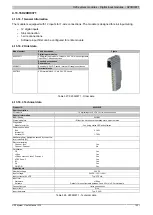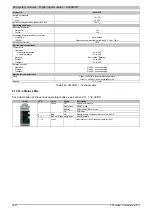
X20 system modules • Digital input modules • X20DI6553
X20 system User's Manual 3.10
1023
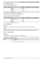
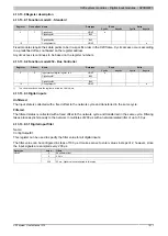
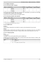
4.13.14.9 Register description
4.13.14.9.1 Function model 0 - Standard
Read
Write
Register
Fixed offset Name
Data type
Cyclic
Acyclic
Cyclic
Acyclic
USINT
DigitalInput01
Bit 0
...
...
DigitalInput06
Bit 5
0
1
PowerSupply
Bit 7
●
18
-
USINT
●
Fixed modules require their data points to be in a specific order in the X2X frame. Cyclic access occurs according
to a predefined offset, not based on the register address.
Acyclic access is continues to be based on the register numbers.
4.13.14.9.2 Function model 254 - Bus Controller
Read
Write
Register
Offset
1)
Name
Data type
Cyclic
Acyclic
Cyclic
Acyclic
Input status of digital inputs 1 to 6
USINT
DigitalInput01
Bit 0
...
...
DigitalInput06
Bit 5
0
0
PowerSupply
Bit 7
●
18
-
USINT
●
1)
The offset specifies where the register is within the CAN object.
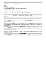
4.13.14.9.3 Digital inputs
Unfiltered
The input state is collected with a fixed offset to the network cycle and transferred in the same cycle.
Filtered
The filtered status is collected with a fixed offset to the network cycle and transferred in the same cycle. Filtering
takes place asynchronously to the network in multiples of 200 µs with a network-related jitter of up to 50 µs.
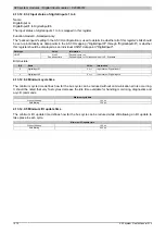
4.13.14.9.3.1 Digital input filter
Name:
ConfigOutput01
This register can be used to specify the filter value for all digital inputs.
The filter value can be configured in steps of 100 μs. It makes sense to enter values in steps of 2, however, since
the input signals are sampled every 200 μs.
Data type
Value
Filters
0
No software filter
2
0.2 ms
...
...
USINT
250
25 ms - Higher values are limited to this value
Summary of Contents for X20 System
Page 2: ......

