・Do not disassemble or modify our products. It may cause a malfunction, fire, electric shock, etc., or cause serious damage.
In addition, the warranty will be void if the product is disassembled or modified.
・ If you are in an abnormal condition such as smoke, abnormal noise, or strange odor, discontinue use immediately as there is
a risk of malfunction, fire, electric shock, or accident.
・Be sure to use accessories and specified parts. If you do not use it, it may cause malfunction, accident, malfunction, fire, etc.
・If you add or move equipment, please check the installation conditions again.
・When disposing of this product, dispose of it as industrial waste.
■
About product handling
Other notes
Other notes
・The control communication device installed in the product corresponds to a "weak radio station (weak radio wave
device)", so the Minister of Internal Affairs and Communications' radio station permit (diploma) is not required.
However, please be careful when operating it as it may affect electronic devices and medical devices (pacemakers, etc.).
■
Standards and regulations
・A remote sensor system is a system that supplies and transmits power and signals in a non-contact manner. Please do not use it
for any purpose other than this purpose.
・Design with the combination described in the instruction manual or user's guide. Opposition in any other combination may
cause malfunction or damage.
・Use a constant voltage power supply such as a switching power supply.
(If a power supply with ripples above the rating, such as a full-wave rectified power supply, is used, it may cause malfunction.)
・If the power supply exceeds the rated voltage, there is a risk of overheating and ignition.
Before supplying power, be sure to check that the power supply is specified in the specifications.
・Design it so that it can be used under the wiring and surrounding environment conditions specified in the specifications. Also,
design to satisfy the "transmission distance", "center offset", "Output voltage", and "Output current". Designs outside the
specifications may cause unexpected malfunctions, troubles, and malfunctions due to deterioration of internal parts.
・When wiring for installation, maintenance, failure, etc., be sure to check that the main breaker (power panel) is cut before
performing the work. If you work while the line is live, you may get an electric shock or malfunction.
・As with other electronic devices, inrush current may be generated when the system starts up, so please set the power
supply in consideration of the inrush current.
・Design the system so that the entire system works safely even if the external power supply is abnormal or the product fails.
・Please be careful about the influence on the material degradation due to the installation environment and the intrusion of
foreign material. Especially when using it outdoors, please install it with less influence from ultraviolet rays.
Product failures due to mishandling are increasing.
Please be sure to read this manual, and if you have any concerns,
please contact the following before energizing.
https://www.b-plus-kk.jp/ E-mail [email protected]
Precautions for installation and design
・Please note that the contents and specifications of this manual are subject to change without notice.
If you have any questions about the contents of this manual, please contact us.
■ Be sure to check it as there are various dangers such as failure if it is installed incorrectly.
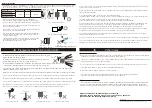
・To avoid heat generation and ignition due to induction heating, do not put metal
objects between the operating heads.
・To avoid heat generation and unexpected accidents, remove metal chips and
cutting chips from the transmission surface of the head.
・To avoid damaging the product due to abnormal heat generation, do not hold the transmission distance
/ center offset / overload condition outside the specifications for a long time.
・ Impact and external noise may cause malfunction or failure. Route the cable away from power lines and high-voltage
equipment without giving a shock. (Fig. 5)
・Make sure that the total current consumption of the connected devices does not exceed the Output current value.
・In order to consider and reduce the self-heating of this product, take measures so that it can be used below the specified ambient temperature.
・To reduce the effect of self-heating (heat dissipation), it is recommended to mount it on metal using case mounting screws.
・If it is installed in a place where it is exposed to direct sunlight or hot air from a heater, it may cause a fire or malfunction. (Fig. 6)
・If you apply power to the Remote part or energize either one with the Base part facing each other, a failure may occur. (Fig. 7)
・Please use in an environment where it is not exposed to organic solvents or liquids containing them. (Fig. 8)
impact
Power lines and high-voltage equipment
noise
(+_+)
(+_+)
24V DC
(+_+)
Direct sunlight and hot air
Energized by facing each other
Liquids such as organic solvents
(Fig. 6)
(Fig. 7)
(Fig. 8)
(Fig. 5)
(Fig. 2) Cable bending radius
Type code
A
(Surroundings)
B
(depth) C(Parallel installation)
RS24T-424-PU-_ _
30mm
30mm
165mm
RS24E-424N-PU-_ _
RS24E-424P-PU-_ _
・When wiring the cable by bending it, use the cable outlet.
Install so that the cable is straight (approximate: about 10 mm)
Install the cable with a bending radius of 50 mm or more. (Figure 2)
・Excessive force on the cable during installation to avoid excessive
stress Please do not pull with.
・Fix the cable so that the sensor, the base of the sensor, and the
cable itself are not shaken or shocked.
・Since metal overheating and internal elements may be damaged,
install the Base part so that it does not face metal, and then
turn on the power. (Fig. 3)
・
If foreign matter get inside the device from the end of the cable,
it may cause fire, smoke, fire, electric shock, or malfunction
due to malfunction or short circuit. (Fig. 4)
Installation method
Metal facing output
(Fig. 3)
(Fig. 4)
(Fig. 1) Arranged with a space
metal
moisture
C
(^_^)
(^_^)
Top view
Side view
A
B
金属
A
A
金属
50mm
A
A
A
A
金属
A
A
金属
metal
metal
((+_+))
metal
Power application
Base part Base part
Remote part
Foreign material
Foreign material invades inside the sensor
Base part
・
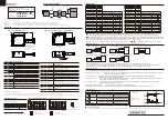
To avoid the influence of surrounding metals and mutual interference between products, be sure to open a space larger
than the value shown in the table below. In addition to the mounting surface, only one surface of A (periphery) can
be in contact with metal. (Fig. 1) The screw tightening torque is 1.5N・m.
(+_+) (+_+)
(+_+)


