


2
Smart Phone Control Kit Manual
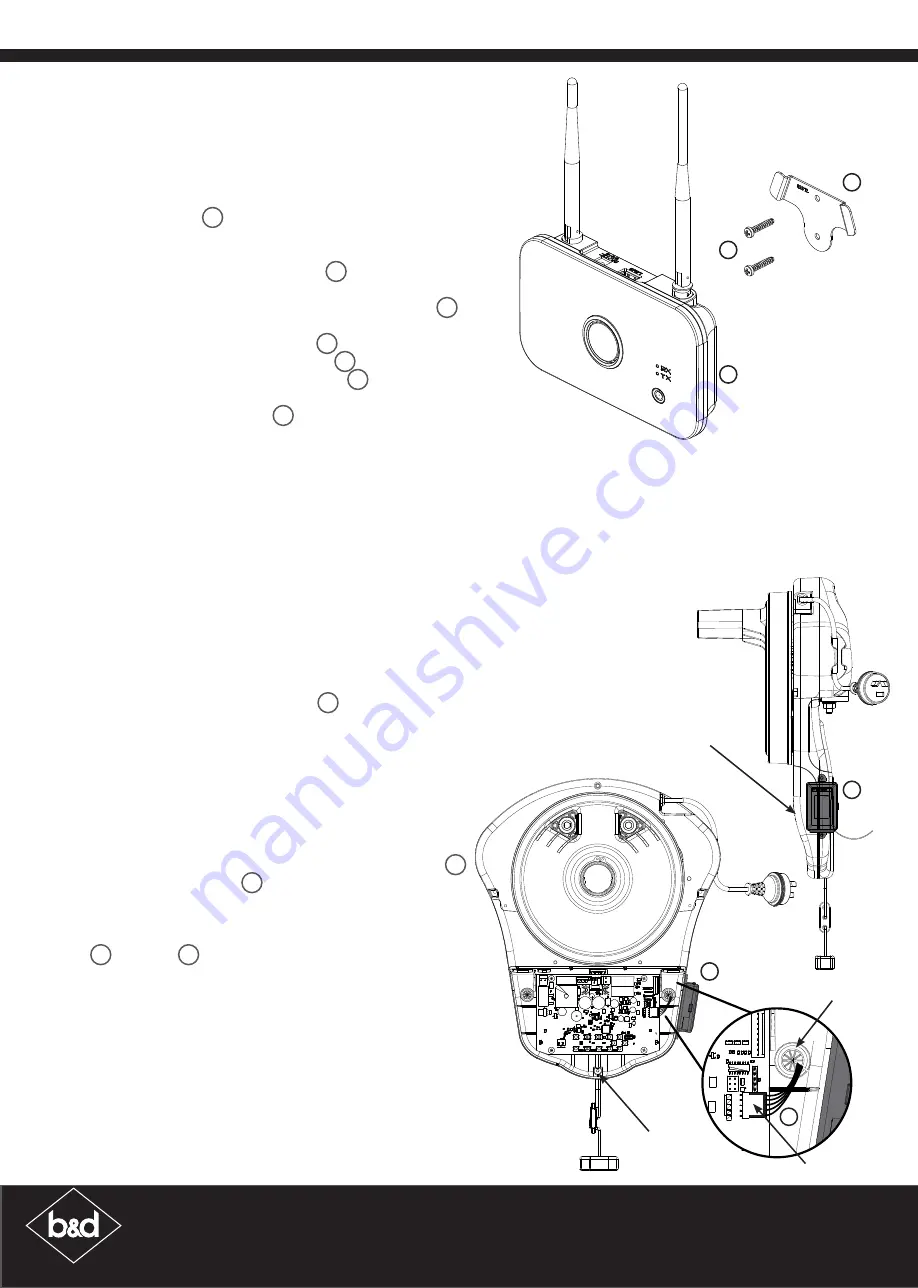
Roller Door Opener Set Up
Powerdrive
Preparation of Opener
a. Disconnect the power supply to the opener.
b. Remove the light diffuser via screw at the bottom.
c. Remove the grommet out of the back cover.
d. Cut (1) one side of the grommet with a knife or scissors.
e. Slide the network timing harness
7
into the cut in the
grommet.
f. Refit grommet to back cover by sliding the harness
through hole before fitting grommet.
g. Connect the harness to the network pin on the control
board.
h. Refit the light diffuser.
Mount and connect Transceiver
a. Plug the other end of the harness into the transceiver
6
.
b. Place the transceiver
6
on the side of the opener to
the black, back cover so that the screw holes on the
transceiver line up with those on the back cover.
c. Secure transceiver using the (2) two Taptite M4 x 12 screws
8
or velcro
9
.
Re-setup and Test the Opener
a. Reconnect power and remove the button cover.
b. Setting Limits:
i. If limits have not been set, follow the openers installation
sheet to set limits.
ii. If limits were set previously, clear limits and follow
openers installation sheet to set limits.
c. Refer to the Smart Phone Control Kit User Guide to set up
network capabilities.
7
6
6
Network Pin
Light diffuser
Grommet
Light diffuser
screw
Smart Hub Set Up
Mounting the Hub
a. Determine whether you are going to wall mount the
hub.
i. If hub is to be placed on bench, simply connect to
power supply
2
, turn on and proceed to installing
the Transceiver.
ii. If hub is to be wall mounted follow steps below.
b. To wall mount - Use wall bracket
3
as template to
mark where to drill holes. Pre-drill holes.
i. For plaster walls - insert (2) two Plastic wall plugs
4
into holes, place wall bracket over holes and affix
with (2) two self tapping screws
5
.
ii. For brick walls - place wall bracket
3
over holes and
affix with (2) two self tapping screws
5
.
c. Slide the hub over the bracket.
d. Connect the power supply
2
and turn on.
1
3
5
This device must be connected to power at all times. DO NOT disconnect power after setup.