background image

A1 B

ASIC - c

onnection diagr

am without REL-4

A1

ELECTRO-MECHANICAL SECURITY LOCK

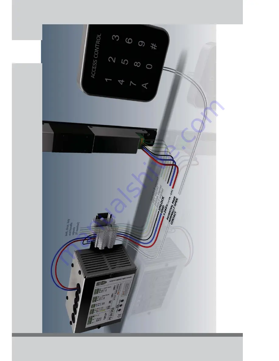
Connection without REL-4 interface:

The unlock impulse is a NO contact, which
bridges pin 2 and 3 on the lock.

In order to guarantee the correct
functioning of the lock 24Vdc (+/-5%) / 2.5A
has to arrive at the lock. We recommend
using our PS24D52 power supply and
BB25LSZH cable (2x1.5mm² + 5x0.22mm²).
The maximum distance between the power
supply and the lock is 25m.

Summary of Contents for A1 Series

Page 1: ...WWW BB LOCKS COM INSTRUCTION MANUAL A1 SERIES...

Page 2: ...igned security escutcheons SE 17 SE 22 SEK 17 SEH 17 SEH 22 and SEHK 17 areavailable optional availableforboth17mmand22mmcylinders availableinbacksetsof25 30 35 50 60mm SA SX SEmodels availableinbacks...

Page 3: ...High resistance 96h 25 C to 70 C level 2 Security Very high security with drill resistance Security electrical function Status indication Security electrical manipulation Electrostatic discharge EN 61...

Page 4: ...thefollowingleverhandles SEH 17 SEH 22 Category of use High frequency of use little care chance of incidence and misuse Durability 200 000 test cycles Door mass up to 200 Kg Suitebility for use on fir...

Page 5: ...OEPN900II IV Push barECOEPN950 availableonourwebsite A1lockserieswithhandle IncombinationwithPush bar Category of use High frequency of use little care chance of incidence and misuse Durability 200 00...

Page 6: ...SE ME AVAILABLE BACKSETS 25 30 35 50 60 mm AVAILABLE BACKSETS 35 60mm SANOCYL SA SX SE unlocked without power without cylinder block unlocked without power with cylinder block mechanical opening alway...

Page 7: ...e Lockedwithoutpower Mechanicalopeningwithkeyisalways possiblefrombothsides Mechanicalopeningwiththehandleisalwayspossiblefromthe secureside The handle on the inside mechanically retracts the locking...

Page 8: ...dandretracted thisshouldbetested afterinstallationoftherubbersontheprofile Make sure the holes for inserting the cylinder are large enough so the cylinder can be easily installed withoutbeingforced On...

Page 9: ...ptions to a door when you are on site we have developed Baseplate Fixation Blocks Using these blocks the A1 lock will end up flush mounted on the profile whenprofileusedis2mm BFB 1 In case it is impos...

Page 10: ...Notes A1 ELECTRO MECHANICAL SECURITY LOCK...

Page 11: ...connects pin 2 GND and pin 3 to unlock black 0 22 mm 0 22 mm 0 22 mm 0 22 mm 0 22 mm transistorswitch to GND when bolt is locked max charge 100mA pin 5 DOOR SIGNAL transistorswitch to GND when door i...

Page 12: ...ing from the lock into potential free contacts It also facilitates the connectionoftheaccesscontrol In order to guarantee the correct functioning of the lock 24Vdc 5 2 5A has to reach the lock We sugg...

Page 13: ...blue black pin 4 BOLT SIGNAL brown yellow pin 6 KEY SIGNAL green grey pin 1 BOLT common pin 2 BOLT locked NO pin 3 BOLT unlocked NC pin 4 DOOR common pin 5 DOOR closed NO pin 6 DOOR open NC pin 7 KEY...

Page 14: ...face The unlock impulse is a NO contact which bridgespin2and3onthelock In order to guarantee the correct functioning of the lock 24Vdc 5 2 5A has to arrive at the lock We recommend using our PS24D52 p...

Page 15: ...Voeding massa Ontgrendel ingang Schoot uitgang Deur uitgang Sleutel uitgang Kruk uitgang SLOT MET KRUK It is possible to mount multiple A1 locks on 1 door in a master slave configuration to obtain a m...

Page 16: ...Production and sales Uilenbaan 88 unit 3 2160 Wommelgem Belgium Tel 32 3 326 36 30 Fax 32 3 326 38 33 E mail info bb locks com B B LOCKS b v b a...

Reviews: