MAXIMAT LW C...
Detection sensor
Glass carbon
Probe tube
PE-HD (polyethylene)
Cap dia.63 mm (...CZD)
PVC (polyvinyl chloride)
Bracket
PVC (polyvinyl chloride)
Pg fitting
PA (polyamide)
Seal / Pg fitting
NBR (perbunan)
Measuring cable
PVC (polyvinyl chloride)
MAXIMAT LW C25...
Detection sensor
Glass carbon
Probe tube
PE (polyethylene)
Cap dia. 32 mm(...CZD)
PVC (polyvinyl chloride)
Bracket
PVC (polyvinyl chloride)
Pg fitting
PA (polyamide)
Seal / Pg fitting
NBR (perbunan)
Measuring cable
PVC (polyvinyl chloride)
INSTALLATION
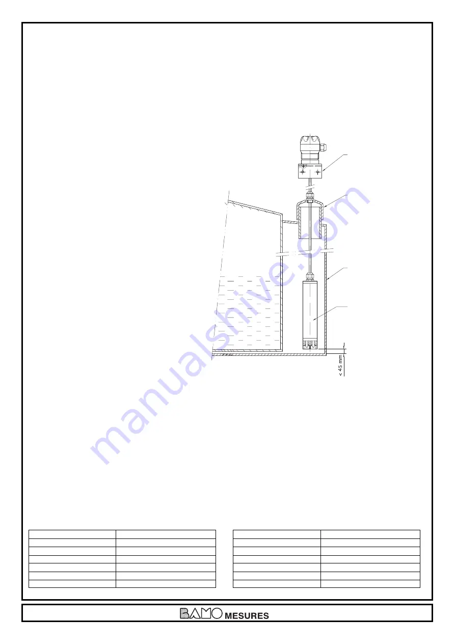
The leakage sensor’s probe is suspended such that it hangs into the catch basin of the storage tank to be monitored.
The probe may make contact with the outside wall of the catch basin, or may stand on its floor.
The cable must be secured such that the probe is always positioned vertically.
The connector cable between the probe and the measuring transducer is pulled through the Pg fitting mounted to the bracket or the
cap until the portion of the cable inside the catch basin holds the probe in the vertical position.
When installed in a free-hanging manner, it must be assured that the connector cable is only pulled far enough through the
adjustor fitting to allow for a maximum clearance of 45 mm between the probe and the catch basin floor, so that the leakage
alarm is triggered at a maximum fill-level of 50 mm.
If the MAXIMAT LW CZ0 variant is used, other suitable mounting components must be used in an appropriate way.
MOUNTING EXAMPLES
Leakage sensor position
For applications involving storage tank catch
basins, the probe must be installed such that the
alarm signal is triggered at a fill-level of 50 mm
or less.
Catch basins, storage tank
The leakage probes are installed inside catch
basins. If the bottom of the probe is in contact with
the floor of the catch basin, the alarm signal is
triggered when the liquid reaches a fill-level of
approximately 5 mm.
555 M1 03 D
07-03-2007
Page 3
PERIODIC TESTING
The leakage probe must be tested for correct functioning at reasonable intervals, although not less than once a year. It is the
sole responsibility of the user to select the utilised test type, as well as a testing interval within the prescribed timeframe.
Testing must be performed which substantiates flawless functioning of the leakage sensor, and correct interaction with all
other associated components. This is assured by means of suitable simulation of a leak, or the physically measured effect
which causes triggering of the alarm signal. If correct functioning of the leakage sensor can be established by other means
(exclusion of function impairing errors), testing can be executed by simulating the appropriate output signal. Further details
concerning test methods are included, for example, in directive VDI / VDE 2180, page 4.
COMPONENT MATERIAL
In the event of a tank leak, the leakage sensor (probe and probe tube) comes into contact with the stored liquid, or vapours and
condensate resulting there for. For this reason, leakage sensor materials must be selected which are adequately resistant to the
liquid to be monitored.
Tank
Fastening angle
Cap with adjustable
thread joint
Catch basin
Sensor


