background image


Page 26 


6.3


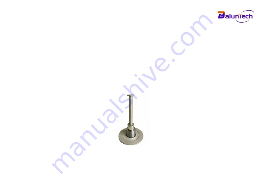
PISTON RE-ASSEMBLY 

1.


Holding the piston by the larger “head” end, carefully introduce the piston into the underside of the cylinder, and 
push gently through (the piston will normally slide freely through due to its own weight). Never force the piston 
into its cylinder or damage will result. If resistance continues, re-clean piston, cylinder, or both. If, after repeated 
cleaning, the piston still will not slide freely within the cylinder, then permanent damage may have occurred. In 
which case, the parts should be returned to the factory for evaluation or replacement.


2.


Stand assembly upright on a clean, hard, stable surface, ensure that the mass carrier is clean (especially the 
central mounting hole), and place on the tapered end of the piston. Tap lightly using the palm of the hand to 
locate on the taper.


3.


Carefully screw the assembly into the instrument, ensuring that the sealing rings is clean and undamaged, and 
correctly re-fitted.


Piston and cylinder unit 

Summary of Contents for BL506

Page 1: ...User Manual Model BL506 Vacuum Deadweight Tester ...

Page 2: ...gulations plus the safety instructions provided in the operating instructions are complied with We do not accept liability for any damage caused by improper use or incorrect operation Please ensure that all persons operating the device have read and understood the operating instructions Keep these operating instructions in a safe place so that they are accessible at all times when needed If you re...

Page 3: ...REMENTS 9 4 SETTING UP THE DEAD WEIGHT TESTER 11 5 OPERATION 16 5 1 PREPATATION 16 5 2 VACUUM CALIBRATION OPERATION 16 5 3 PRESSURE CALIBRATION OPERATION 21 6 MAINTENANCE 25 6 1 PISTON DISASSEMBLY 25 6 2 PISTON CLEANING 25 6 3 PISTON RE ASSEMBLY 26 7 TROUBLESHOOTING 27 ...

Page 4: ...st a little swing of the masses 1 2 OPERATING PRINCIPLE A deadweight tester is based on a high accurate manufactured piston and cylinder assembly This cylinder is mounted in a column The piston can rotate and freely move up and down Accurately calibrated masses are loaded on top of the vertically mounted piston A pressure is applied on the bottom of the piston to lift the piston with masses This c...

Page 5: ... air at the reference level the typical air density value is 1 2 kg m ρ2 The density of mass ρ value of stainless steel 7 93x10 kg m3 ρ value of carbon steel 7 8x10³kg m3 So Effective area at zero pressure t 20 m λ Pressure distortion coefficient piston cylinder system MPa Po It is the pressure value when piston system doesn t be deformed can be instead by P MPa α1 Thermal expansion coefficient of...

Page 6: ...sters the effective area is determined by cross floating with a known reference primary standard deadweight tester The exact pressure can be calculated As per the formula of the item 1 4 compensation factors are listed for air buoyancy local gravity surface tension of the used oil and temperature and pressure expansion of the piston cylinder assembly All necessary data are listed in the calibratio...

Page 7: ...m H x 650mm L x 500mm D Pump dimension 225mm H x 455mm L x 380mm D Tester weight Appro 25kg Pump weight Appro 15kg Recalibration Every 2 5 years 2 2 PRESSURE RANGE SELECTABLE SHEET P N Pressure Accuracy Area Kn factor Mass Set KYQZ100 100 100 kPa 0 05 0 02 0 01 0 005 10cm2 10kPa kg 10kg 10kg KYQZ160 100 160 kPa 0 05 0 02 0 01 0 005 5 cm2 20kPa kg 5kg 8kg KYQZ250 100 250 kPa 0 05 0 02 0 01 0 005 5 ...

Page 8: ...essure 10kPa 5kPa 5kPa 10kPa 20kPa Pieces 9 2 2 5 5 KYQZ250 100 250 kPa 5kPa Pressure 10kPa 5kPa 5kPa 10kPa 20kPa 50kPa Pieces 9 2 2 2 1 4 KYQZ400 100 400 kPa 5kPa Pressure 10kPa 5kPa 5kPa 10kPa 20kPa Pieces 9 2 2 15 12 KYQZ600 100 600 kPa 5kPa Pressure 10kPa 5kPa 5kPa 10kPa 20kPa 50kPa 100kPa Pieces 9 2 2 2 1 1 5 KYQZ1M 100 1000 kPa 5kPa Pressure 10kPa 5kPa 5kPa 10kPa 20kPa 50kPa 100kPa Pieces 9 ...

Page 9: ...Page 6 2 4 SCOPE OF DELIVERY ...

Page 10: ...Page 7 2 5 INSTRUMENT OUTLINE FOR VACUUM DEADWEIGHT TESTER BASE ...

Page 11: ...Page 8 2 6 INSTRUMENT OUTLINE FOR MANUAL PUMP ...

Page 12: ...whenever testers are being used for instrument calibration Because a leak in the tester s high pressure line can release an explosive mist of oil proper fire extinguishers should be immediately available Pre load the tester s piston with weights before applying pressure to the gauge Otherwise shock from the pressure can dislodge the piston retainer ring allowing the piston to fly out of the tester...

Page 13: ...l must wear reinforced safety shoes to prevent injury Before bleeding pressure from the tester the valve at the pressure source should be closed The instrument s pressure should then be slowly bled to atmosphere If a vent valve is unavailable the fitting at the tester should be carefully and slowly loosened This procedure is to create a small leak minimizing the volume of oil that will enter the i...

Page 14: ...e pump on a firm level base make the bubble level in the middle position by adjusting the three bottom feet of vacuum deadweight tester 4 2 Remove the bell jar from the vacuum deadweight tester base check whether the sealing ring in the groove Make sure the sealing ring is not aged or broken If not please replace it with new one ...

Page 15: ...R FINGER TO TOUCH THE PISTON SUFACE The natural dermal grease can cause a jamming of the piston cylinder system 4 4 Use hand to screw out the knurled pressure cap of piston cylinder unit check whether if the internal seal ring is in good condition Make sure the sealing ring is not aged or broken If not please replace it with new one ...

Page 16: ... THE PISTON SURFACE The natural dermal grease can cause a jamming of the piston cylinder system 4 5 Put the cylinder into the base with the lettered end facing up as following left picture hand tight the knurled pressure cap to the mechanical stop on the outside of the cylinder as following right picture ...

Page 17: ...olding the piston by the larger head end carefully introduce the piston into the underside of the cylinder and push gently through as following left picture Never force the piston into its cylinder or damage will result Fully tight and three bottom dowel screws as following right picture ...

Page 18: ... port negative port with flexible connection hose between vacuum deadweight base and manual pressure pump as following left picture Connect the electric vacuum pump with manual hand pump with flexible connection hose as following right picture ...

Page 19: ...on of the deadweight tester as this results in unpredictable errors Room temperature needs to be stable between 23 2 C during the time the deadweight tester is used to avoid uncertainties due to the thermal expansion coefficients of the piston cylinder and adiabatic effects in the measuring system Air movement around the deadweight tester should be avoided Check if the bubble level is in the cente...

Page 20: ...e check whether the sealing ring is in the groove Make sure it is not aged or broken If not please replace it with new one Step 3 Carefully take out the piston cylinder unit from the vacuum base put it on the table carefully DO NOT USE YOUR FINGER TO TOUCH THE PISTON SUFACE ...

Page 21: ...otection tube left direction is to loose and put it on the table Step 5 Place the piston vertically and carefully DO NOT USE YOUR FINGER TO TOUCH THE PISTON SUFACE The natural dermal grease can cause a jamming of the piston cylinder system ...

Page 22: ...ump Push the pressure vacuum switch inside on the manual pressure pump Put the bell jar on the base Step 7 Install the unit under test UUT on the one of three quick connectors close the vent valve open the shut off valve closes the isolation valve for electric vacuum pump Put the first calculated mass on the mass carrier ...
Page 23: ...acuum till the piston goes up rotate the piston clockwise direction Use wheel pressure regulator to fine adjust the desired vacuum make sure the piston is between the two piston position make lines on the bell jar Step 13 Repeat the step 11 12 till the measure vacuum to 95kPa Step 14 For 100kPa vacuum we need the help from electric vacuum pump EVP Open the isolation valve of EVP power on the EVP t...

Page 24: ...the piston to make sure its position is in the range of two mark lines on the bell jar records the measuring value Step 16 Repeat the step 15 to finish the rest of calibration points in the down process 5 3 PRESSURE CALIBRATION OPERATION Step 1 Calculate the weight s pressure and related quantities Step 2 Check if the bubble level is in the center if not level the instrument with the 3 adjustable ...

Page 25: ...htly DO NOT USE YOUR FINGER TO TOUCH THE PISTON SUFACE The natural dermal grease can cause a jamming of the piston cylinder system But user can touch the thin pole when the piston is needed to rotate or handle Step 5 Hand tight the piston protection tube right direction is to screw inside ...

Page 26: ... under test UUT on the one of three quick connectors of manual hand pump close the vent valve open the shut off valve and close the isolation valve for electric vacuum pump Use flexible hose to connect the positive port on the vacuum deadweight tester to the manual pressure pump Pull the pressure vacuum switch outside on the manual pressure pump make sure the applied pressure will be positive pres...

Page 27: ...operation is for up process of pressure calibration For down process pressure calibration firstly take off one weight open the vent valve to release the air slowly Quickly close the vent valve if it is closing the desired value Use wheel pressure regulator to fine adjust the pressure rotate the piston to make sure its position is not ahead of the marked step on the pressure cap Close the shut off ...

Page 28: ...non fluffing non abrasive lint free tissue or absorbent cloth Hold the piston by the larger head end and rub the tissue back and forth along its length 2 To remove all traces of contamination the piston can be cleaned in a suitable solvent 3 After removal from the solvent using a NEW tissue repeat the cleaning procedure in step 4 4 Place piston carefully on a NEW tissue where it will not be damage...

Page 29: ...g the piston still will not slide freely within the cylinder then permanent damage may have occurred In which case the parts should be returned to the factory for evaluation or replacement 2 Stand assembly upright on a clean hard stable surface ensure that the mass carrier is clean especially the central mounting hole and place on the tapered end of the piston Tap lightly using the palm of the han...

Page 30: ...mmediately Do not rotate the piston if it is dirty as permanent damage can occur If the spin sensitivity of a recently cleaned PCU deteriorates quickly then it is likely that the hydraulic or pneumatic system has become contaminated If this is the case the system must be completely dismantled thoroughly cleaned and rebuilt before further calibration is carried out During the normal operation of a ...

Page 31: ...losed and test port connections are correctly made 2 The DUT may be leaking This can be verified by recording the fall rate and comparing it with the fall rate under the same conditions but with the DUT removed and the test port blanked off 3 If the system has been pressurized quickly then sufficient time must be allowed for the instrument to thermally stabilize Continue re floating the piston unt...

Reviews: