background image

7 / 20

0006081531_201203

PYCCKИИ

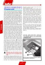
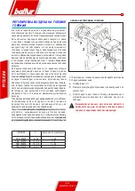
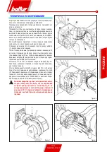
СОЕДИНЕНИЕ ГОРЕЛКИ С КОТЛОМ

МОНТАЖ БЛОКА ГОЛОВКИ

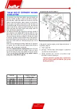
A)    Правильно отрегулируйте положение соединительного 

фланца  5.  Для  этого  ослабьте  винты  6  так,  чтобы 
головка горения вошла в топку на длину, рекомендуемую 
конструктором генератора.

B)  Расположите на стакане изоляционную прокладку (3), а 

между фланцем и прокладкой проложите шнур (2).

C)  Закрепите  узел  головки  (4)  к  котлу  (1)  при  помощи 

установочного штифта, шайб и гаек из комплекта поставки 

(7).

!

  Полностью запломбируйте подходящим материалом 

расстояние между стаканом горелки и огнеупорным 

отверстием внутри дверцы котла.

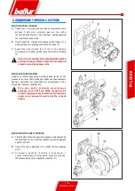
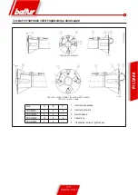
МОНТАЖ ГАЗОВОЙ РАМПЫ

Имеется несколько вариантов монтажа рампы (8, 8a, 9), как 

указано на рисунке сбоку. Выберите наиболее рациональный 

вариант, учитывая структуру рабочего помещения котла и 

откуда идёт газовый трубопровод.

!

  Если  речь  идёт  о  клапанах  значительных 

размеров, напр., DN65 или DN80, предусмотрите 

соответствующую опору во избежание чрезмерных 

нагрузок  на  соединительный  патрубок  газовой 

рампы.

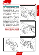
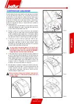
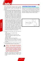
МОНТАЖ КОРПУСА ВЕНТИЛЯТОРА

A)  Расположите полушарнирные соединения, имеющиеся на 

корпусе горелки, так, чтобы они совпали с уже имеющимися 

на узле головки.

B)  Поместите палец шарнира (10) в наиболее подходящее 

место.

C)  Соедините  провода  (розжига  и  ионизации)  с 

соответствующими  электродами,  закройте  шарнир, 

заблокировав горелку посредством винтов (11).

Summary of Contents for TBG 85 ME

Page 1: ...ATING GAS BURNERS WITH ELECTRONIC CAM BT 3 QUEMADORES DE GAS DE DOS ETAPAS PROGRESIVAS MODU LANTES CON LEVA ELECTR NICA BT 3 BT 3 BT 3 ELEKTRON K KAMLI LERLEMEL MOD LASYON K FAZLI GAZ BR L RLER BRULEU...

Page 2: ......

Page 3: ...18 11 2010 Declaration of Conformity We declare that our products BPM BGN BT BTG BTL TBML Comist GI GI Mist Minicomist PYR RiNOx Spark Sparkgas TBG TBL TBML TS IBR IB Variant LX for low NOx emissions...

Page 4: ...r if the owner moves and leaves the equipment make sure that the booklet always goes with the equipment so it can be consulted by the new owner and or installer For all equipment with optionals or kit...

Page 5: ...t law and regulations since incorrect installation may cause damage to person animals or things for which damage the manufacturer shall not can be held responsible Before installation it is advisable...

Page 6: ...TBG 210ME BURNER COUPLING FLANGE 2 2 2 2 INSULATING GASKET 1 1 1 1 STUD BOLTS No 4 M 12 No 4 M 12 No 4 M 12 No 4 M 12 HEXAGONAL NUTS No 4 M 12 No 4 M 12 No 4 M 12 No 4 M 12 FLAT WASHERS No 4 12 No 4 1...

Page 7: ...eration the size of the combustion chamber must correspond to current regulations if not the manufacturers must be consulted MANUFACTURING CHARACTERISTICS The burner consists of the following parts Co...

Page 8: ...NTS 6 Gas train coupling flange 7 Electrical panel 8 Motor 9 Air adjustment servomotor 9a Gas adjustment servomotor OVERALL DIMENSIONS MOD G A1 A2 B B1 B6 C D MIN D MAX E F E L MIN L MAX M H TBG 85ME...

Page 9: ...ory material inside the boiler door with suitable material ASSEMBLING THE GAS TRAIN There are different ways of assembling the valve train 8 8a and 9 as shown in the drawing Choose the most rational p...

Page 10: ...ation joint must be installed upstream of the gas valve as shown in the diagram 1 Manual shut off valve 2 Anti vibration joint 3 Gas filter 4 Minimum gas pressure switch 5 Safety valve 6 Pressure regu...

Page 11: ...amp plate fig 3 Turn the cam 4 so that the plate exerts sufficient pressure on the two cables then tighten the screws that fasten the plate Finally connect the 7 pole plug and the modulation control c...

Page 12: ...entilation phase and after 3 seconds the safety and main valves open in sequence The gas reaches the combustion head mixes with air supplied by the fan and ignites The gas supply is regulated by the b...

Page 13: ...tch With the control equipment receiving electrical power the programmer will cause the burner to start up as described in chapter Operation description For burner adjustment refer to the supplied ins...

Page 14: ...flame on tripping the gas pressure switches opening the circuit will shut down the burner immediately When testing the burner it is very important to check that the pressure switches are working prope...

Page 15: ...0P 150PN 150ME TBG 210P 210PN 210ME TBG 85P 85PN 85ME Mod A B C TBG 85ME 5 3 3 TBG 120ME 5 5 TBG 150ME 15 5 6 TBG 210ME 5 5 ENGLISH 1 Ionisation electrode 2 Ignition electrode 3 Flame disk 4 Mixer 5 G...

Page 16: ...ixture and flame stability High air pressure upstream of the disk may be necessary to prevent flame fluctuations this is particularly essential when the burner works on the furnace that is pressurised...

Page 17: ...ls of the respective electrodes unscrew completely the nut 4 and tighten the screw 5 moving it forward inside the gas delivery fitting 8 far enough to permit subsequent dismantling of the mixing unit...

Page 18: ...onisation current cannot be checked Check the efficiency of the earth at the terminal concerned in the equipment and at the earth connection of the electric system The equipment goes into lock out gas...

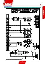
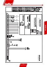
Page 19: ...17 20 0006081531_201203 ENGLISH WIRING DIAGRAM...

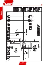
Page 20: ...18 20 0006081531_201203 ENGLISH START FOR RECORDER MINIMUM IONISATION CURRENT 1 5 A...

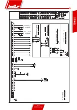
Page 21: ...19 20 0006081531_201203 ENGLISH WATER TEMPERATURE PRESSURE PROBE RELAY COMMAND INPUT COMMAND INPUT 0 4 20 mA OUTER TEM PERATURE PROBE GAS TEMPERA TURE PROBE POSSIBLE...

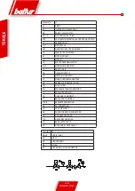
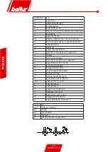
Page 22: ...RNAL SHUTDOWN INDICATOR LIGHT H1 OPERATION LIGHT K1 MOTOR RELAY MV MOTOR N1 ELECTRONIC REGULATOR P M GAS MAX PRESSURE SWITCH P1 HOUR METER PA AIR PRESSURE SWITCH Pm GAS MIN PRESSURE SWITCH S1 ON OFF S...

Page 23: ...E MAIL info baltur it 18 11 2010 Declaraci n de conformidad Declaramos que nuestros productos BPM BGN BT BTG BTL TBML Comist GI GI Mist Minicomist PYR RiNOx Spark Sparkgas TBG TBL TBML TS IBR IB Varia...

Page 24: ...ro de instruccionesest siempreconelaparatoparaquepuedaserconsultado por el nuevo propietario y o instalador Para todos los aparatos con elementos opcionales o kits incluidos los el ctricos hay que uti...

Page 25: ...ento el aparato el personal cualificado profesionalmente tiene que controlar a la estanqueidad en el tramo interior y exterior de los tubos de abastecimiento del combustible b la regulaci n del caudal...

Page 26: ...E 1 1 1 1 PRISIONEROS N 4 M 12 N 4 M 12 N 4 M 12 N 4 M 12 TUERCAS EXAGONAL NUTS N 4 M 12 N 4 M 12 N 4 M 12 N 4 M 12 ARANDELAS PLANAS N 4 12 N 4 12 N 4 12 N 4 12 CARACTER STICAS T CNICO FUNCIONALES Fun...

Page 27: ...n la normativa vigente de lo contrario hay que consultarse con los fabricantes CARACTER STICAS CONSTRUCTIVAS El quemador est compuesto por Entrada del aire comburente dotado de inserto de material fon...

Page 28: ...RICO 6 Brida de conexi n a la rampa del gas 7 Cuadro el ctrico 8 Motor 9 Servomotor de regulaci n del aire 9a Servomotor de regulaci n del gas DIMENSIONES TOTALES MOD A A1 A2 B B1 B6 C D M N D M X E F...

Page 29: ...ro de la tapa de la caldera MONTAJE DE LA RAMPA DE GAS Son posibles diversas soluciones de montaje 8 8a 9 de la rampa de las v lvulas como se muestra en el dibujo de al lado Seleccionar la posici n m...

Page 30: ...n manual y una junta antivibrante colocados seg n lo que se indica en el esquema 1 V lvula de detecci n manual 2 Junta antivibrante 3 Filtro del gas 4 Pres stato de presi n m nima del gas 5 V lvula d...

Page 31: ...que la placa ejerce una adecuada presi n en los dos cables luego apretar los tornillos que fijan la placa Conectar al final la clavija de 7 polos y los cables de mando de modulaci n los alojamientos...

Page 32: ...iento de la leva electr nica BT 3xx leer cuidadosamente las instrucciones indicadas en el manual que acompa a el equipo Se llama funcionamiento de dos etapas progresivas puesto que el pasaje entre la...

Page 33: ...car un man metro con escala adecuada si la entidad de la presi n prevista lo permite es preferible utilizar una herramienta de columna de agua no utilizar herramientas de manecillas para presiones mod...

Page 34: ...ando el pres stato detecta una presi n interior a la de su regulaci n La regulaci n de los pres statos de presi n del gas m nima y m ximatieneentoncesquellevarseacaboenelactodelprueba del quemador seg...

Page 35: ...G 210P 210PN 210ME TBG 85P 85PN 85ME Mod A B C TBG 85ME 5 3 3 TBG 120ME 5 5 TBG 150ME 15 5 6 TBG 210ME 5 5 ESPA OL 1 Electrodo de ionizaci n 2 Electrodo de encendido 3 Disco de la llama 4 Mezclador 5...

Page 36: ...le tener una elevada presi n del aire antes del disco para evitar pulsaciones de llama esta condici n es pr cticamente indispensable cuando el quemador trabaja en una c mara de combusti n presurizada...

Page 37: ...pletamente la tuerca 4 y atornillar el tornillo 5 haci ndole avanzar dentro del empalme de env o del gas 8 durante un tramo suficiente como para garantizar el sucesivo desmontaje del grupo de mezcla U...

Page 38: ...esulta efi ciente no hay corriente de ionizaci n Comprobar la eficiencia de la masa del borne apropiado del aparato y de la conexi n de tierra de la instalaci n el ctrica El aparato se bloquea el gas...

Page 39: ...17 20 0006081531_201203 ESPA OL ESQUEMA EL CTRICO...

Page 40: ...18 20 0006081531_201203 ESPA OL ARRANQUE PARA REGISTRADOR CORRENTE M NIMA DE IONIZACI N 1 5 A...

Page 41: ...19 20 0006081531_201203 ESPA OL TEMPERATURA DEL AGUA SONDA DE PRESI N INGRESO MANDO DE REL ENTRADA MANDO0 4 20 mA SONDA DE TEMPERATU RA EXTERNA SONDA DE TEMPERATU RA DEL GAS POSIBLE...

Page 42: ...MIENTO K1 REL DEL MOTOR MV MOTOR N1 REGULADOR ELECTR NICO P M PRES STATO DE M XIMA P1 CUENTAHORAS PA PRES STATO DEL AIRE Pm PRES STATO DE M NIMA S1 INTERRUPTOR DE MARCHA PARADA S2 PULSADOR DE RESET SG...

Page 43: ...baltur com E MAIL info baltur it 18 11 2010 D claration de Conformit Nous d clarons que nos produits BPM BGN BT BTG BTL TBML Comist GI GI Mist Minicomist PYR RiNOx Spark Sparkgas TBG TBL TBML TS IBR...

Page 44: ...e dernier toujours v rifier que la notice accom pagne l appareil afin qu il puisse tre consulter par le nouveau propri taire et ou par l installateur Pour tous les appareils avec options ou kit y comp...

Page 45: ...les v ri fications suivantes par du personnel qualifi a le contr le de l tanch it de la partie interne et externe des tuyaux d arriv e du combustible b la r glage du d bit du combustible en fonction...

Page 46: ...ATION DU BR LEUR 2 2 2 2 JOINT ISOLANT 1 1 1 1 GOUJONS N 4 M 12 N 4 M 12 N 4 M 12 N 4 M 12 ECROUS N 4 M 12 N 4 M 12 N 4 M 12 N 4 M 12 RONDELLES PLATES N 4 12 N 4 12 N 4 12 N 4 12 C A R A C T E R I S T...

Page 47: ...ux normes en vigueur dans le cas contraire consulter les constructeurs CARACTERISTIQUES DE CONCTRUCTION Le br leur est constitu par Entr e d air comburant quip e avec insert en mat riel phono absorban...

Page 48: ...ECTRIQUE 6 Bride de fixation de la rampe gaz 7 Tableau lectrique 8 Moteur 9 Servomoteur de r glage de l air 9a Servomoteur de r glage du gaz DIMENSIONS D ENCOMBREMENT MOD A A1 A2 B B1 B6 C D MIN D MAX...

Page 49: ...a porte de la chaudi re MONTAGE DE LA RAMPE GAZ Diff rentes solutions de montage de la rampe des vannes sont possibles 8 8a 9 tel que l illustre le dessin ci contre Choisir la position la plus rationn...

Page 50: ...ne vanne manuelle de barrage et un joint amortisseur dispos s d apr s le sch ma 1 Vanne de barrage manuel 2 Joint amortisseur 3 Filtre du gaz 4 Pressostat de pression minimale du gaz 5 Vanne de s curi...

Page 51: ...6 de mani re ce que la plaquette exerce une pression ad quate sur les deux c bles puis serrer les vis qui fixent la plaquette Connecter enfin la fiche 7 p les et les c bles de commande de modulation l...

Page 52: ...rsque le passage de la premi re la seconde flamme du r gime minimum au maximum pr fix s effectue de fa on progressive tant du point de vue de l apport d air comburant que du point de vue du d bit de c...

Page 53: ...ligne d alimentation du moteur pour inverser le sens de rotation 8 Activer maintenant l interrupteur g n ral L appareillage de commande re oit ainsi la tension et le programmateur d termine l activat...

Page 54: ...u br leur Lorsque le br leur est en fonction flamme allum e l intervention des pressostats de gaz ouverture de circuit d termine imm diatement l arr t du br leur Au moment de l essai du br leur on doi...

Page 55: ...150ME TBG 210P 210PN 210ME TBG 85P 85PN 85ME Mod A B C TBG 85ME 5 3 3 TBG 120ME 5 5 TBG 150ME 15 5 6 TBG 210ME 5 5 FRAN AIS 1 lectrode ionisation 2 lectrode allumage 3 Disque flamme 4 M langeur 5 Tuya...

Page 56: ...ndispensable d avoir une haute pression de l air en amont du disque pour viter les pulsations de flamme cette condition est pratiquement indispensable quand le br leur fonctionne sur un foyer pressuri...

Page 57: ...lectrodes respectifs d visser compl tement l crou 4 et visser la vis 5 en la faisant avancer l int rieur du raccord de refoulement du gaz 8 pour une distance suffisante pour garantir le d montage succ...

Page 58: ...il n y a pas de courant d ionisation V rifier l efficacit de la masse au niveau de la borne de l appareillage et du raccordement la terre de l installation lectrique L appareil se bloque le gaz sort m...

Page 59: ...17 20 0006081531_201203 FRAN AIS SCHEMA ELECTRIQUE...

Page 60: ...18 20 0006081531_201203 FRAN AIS MARCHE POUR ENREGISTREUR COURANT D IONISATION MINIMUM 1 5 A...

Page 61: ...19 20 0006081531_201203 FRAN AIS TEMPERATURE DE L EAU SONDE DE PRESSION ENTREE DE COMMANDE A RELAIS ENTR E DE COMMANDE 4 20 mA SONDE TEMPERATURE EXTERIEURE SONDE TEMPERATURE DU GAZ EVENTUEL...

Page 62: ...ONCTIONNEMENT K1 RELAIS DU MOTEUR MV MOTEUR N1 REGULATEUR ELECTRONIQUE P M PRESSOSTAT DE MAXIMUM P1 COMPTEUR D HEURES PA PRESSOSTAT AIR Pm PRESSOSTAT DE MINIMUM S1 INTERRUPTEUR MARCHE ARRET S2 BOUTON...

Page 63: ...Beyan A a daki r nlerimizin BPM BGN BT BTG BTL TBML Comist GI GI Mist Minicomist PYR RiNOx Spark Sparkgas TBG TBL TBML TS IBR IB Varyant LX d k NOx emisyonlar i in Konut ve sanayi kullan m i in hava f...

Page 64: ...nma k lavuzlar n n da daima cihaz n yan nda olmas n sa lay n z B ylece yeni sahibi ve veya monte eden ki i k lavuzdan yararlanabilir Opsiyonel malzemeler veya elektrik malzemesi dahil kitler de dahil...

Page 65: ...u ger ekle tirilmelidir Yanl kurulum insana hayvana ve e yaya zarar verebilir ki bu a amada retici bu zarardan sorumlu de ildir Br l r kurulumundan nce sistemin d zg n al mas n aksatacabilecek yak t b...

Page 66: ...AN I 2 2 2 2 ZOLASYON CONTASI 1 1 1 1 SAPLAMA CIVATALAR 4 ADET M 12 4 ADET M 12 4 ADET M 12 4 ADET M 12 SOMUNLAR EXAGONAL NUTS 4 ADET M 12 4 ADET M 12 4 ADET M 12 4 ADET M 12 YASSI RONDELALAR FLAT WAS...

Page 67: ...ac n n boyutlar y r rl kteki y netmeli e uygun olmal d r aksi taktirde retici firmalara dan lmal d r YAPISAL ZELL KLER Br l r a a daki par alardan olu maktad r Ses ge irmez malzemeden ek par a ile don...

Page 68: ...z rampas ba lant flan 7 Elektrik paneli 8 Motor 9 Hava reg lasyon servomotoru 9a Gaz reg lasyon servomotoru TAM BOYUTLAR MOD A A1 A2 B B1 B6 C D M N D MAKS E F I L M N L MAKS M N TBG 85ME 610 240 370...

Page 69: ...daki bo lu u uygun malzeme ile tamamen kapat n z GAZ RAMPASININ MONTAJI Yandaki izimde g sterildi i gibi valfler rampas n n farkl montaj z mleri 8 8a 9 m mk nd r Kazan yerinin yap s na g re en rasyone...

Page 70: ...alfiniveanti titre imlibircontay gazvalfinin st ne monte etmek gerekir 1 Man el kesme valfi 2 Anti titre imli conta 3 Gaz filtresi 4 Minimum gaz bas nc manostat 5 G venlik valfi 6 Bas n reg lat r 7 Va...

Page 71: ...kablo zerinde uygun bir bas n uygulayacak ekilde eksantrik mandal 6 d nd r n z plakay sabitleyen vidalar s k t r n z Son olarak 7 kutuplu fi i ve mod lasyon kumanda kablolar n ba lay n z kablolar n yu...

Page 72: ...ndan nce olur bunun s resi yakla k30saniyedir E erhavamanostat yeterlibas n alg lam ise havaland rma faz n n sonunda ate leme transformat r devreye girer ve saniyeden sonra anaveg venlikvalfleris rayl...

Page 73: ...ylece kumanda cihaz gerilimi alg lar ve programlay c leyi in tan m b l m nde anlat ld gibi br l r n devreye al nmas n belirler Br l r n reg lasyonu i in cihaz ile birlikte verilen BT 3xx elektronik k...

Page 74: ...kir lgili reg lasyon par alar zerinde gerekti inde i lem yaparak br l r n durmas n belirlemesi gereken manostat n m dahalesi devrenin a lmas kontrol edilir 14 Alev alg lay c s n n i leyi ini a a daki...

Page 75: ...N 150ME TBG 210P 210PN 210ME TBG 85P 85PN 85ME Mod A B C TBG 85ME 5 3 3 TBG 120ME 5 5 TBG 150ME 15 5 6 TBG 210ME 5 5 T RK E 1 yonizasyon elektrotu 2 Ate leme elektrotu 3 Alev diski 4 Kar t r c 5 Gaz d...

Page 76: ...ve ideal bir kar m ve alev stabilitesi sa lar Alev tepmelerini nlemek i in disk ncesinde y ksek bir hava bas nc olmas gerekebilir br l r bas n l ve veya y ksek termik y ke sahip kazan oca zerinde al...

Page 77: ...yonizasyon kablolar n 3 kard ktan sonra somunu 4 tamamen s k n z ve kar t rma grubunun sonraki montaj n sa lamak i in yeterli bir mesafe boyunca gaz da t m rakorunun 8 i inde ilerleterek viday 5 vidal...

Page 78: ...se iyonizasyon ak m kontrol edilmez Cihaz n zelba lant ucundakiveelektrik tesisat n n toprak ba lant s ndaki topraklaman n etkinli ini kontrol ediniz Cihaz bloke durumuna gidiyor gaz k yor ancak alev...

Page 79: ...17 20 0006081531_201203 T RK E ELEKTR K EMASI...

Page 80: ...18 20 0006081531_201203 T RK E REG LAT R N BA LATMA M N MUM YON ZASYON AKIMI 1 5 A...

Page 81: ...19 20 0006081531_201203 T RK E SU SICAKLIK DERECES BASIN ALGILAYICISI R LEL KUMANDA G R KUMANDA GIRI I 0 4 20 mA HAR C SICAKLIK ALGILAYICISI GAZ SICAKLIK ALGILAYICISI MUHTEMEL...

Page 82: ...HAR C BLOKAJ UYARI LAMBASI H1 LEY UYARI LAMBASI K1 MOTOR R LES MV MOTOR N1 ELEKTRON K REG LAT R P M MAKS MUM MANOSTATI P1 SAAT L ER PA HAVA MANOSTATI Pm M N MUM MANOSTATI S1 MAR DURDURMAANAHTARI S2 S...

Page 83: ...051 684 37 11 Fax 39 051 683 06 86 http www baltur it http www baltur com E MAIL info baltur it BPM BGN BT BTG BTL TBML Comist GI GI Mist Minicomist PYR RiNOx Spark Sparkgas TBG TBL TBML TS IBR IB LX...

Page 84: ...2 20 0006081531_201203 PYCCK BALTUR a b c a b c d e f g...

Page 85: ...3 20 0006081531_201203 PYCCK 2 RC a b c d e a b a b c d...

Page 86: ...2800 2800 2800 1 20 1 60 2 40 3 2 400 6 10 10 16 26 40 230 50 3 400 10 50 IP 40 73 75 5 79 85 78 87 91 94 G 20 85 5 120 7 150 9 211 2 17 24 1 30 2 40 3 500 TBG 85ME TBG 120ME TBG 150ME TBG 210ME 2 2...

Page 87: ...0 100 110 6 8 10 12 14 16 18 20 22 24 26 28 30 32 34 36 38 40 42 44 mn h Metano mn h G P L kW 1200 1300 120 130 46 48 50 1400 1500 1600 16 140 150 160 52 54 56 58 60 62 1700 1800 1900 2000 170 180 190...

Page 88: ...L L M N TBG 85ME 610 240 370 520 380 200 1265 175 400 180 178 280 250 325 M12 190 TBG 120ME 610 240 370 540 380 200 1265 200 450 224 219 320 280 370 M12 235 TBG 150ME 610 240 370 540 380 200 1265 200...

Page 89: ...7 20 0006081531_201203 PYCCK A 5 6 B 3 2 C 4 1 7 8 8a 9 DN65 DN80 A B 10 C 11...

Page 90: ...8 20 0006081531_201203 N 0002910950n2 PYCCK EN676 1 2 3 4 5 6 7 8 9 10 11 12 13 14...

Page 91: ...9 20 0006081531_201203 PYCCK 1 4 1 1 2 2 3 7 2 4 5 3 3 6 7 9 5 10 8 5 9 IP 54 CEI EN60529 4 4 1 5 8 7 4 5 5 9 2 3 4 5 1...

Page 92: ...10 20 0006081531_201203 A B farfallaTBG ME PYCCK 3 RESET 4 B LAMTEC BT 3xx BT 3xx 30 2 200 999 BT 3xx...

Page 93: ...11 20 0006081531_201203 display lamtec BT3xx 3 4 1 2 5 PYCCK 1 2 3 4 RESET 5 1 2 3 4 5 6 7 1 8 BT 3xx 9 200 BT 3xx 10 200 999 CO 11 12...

Page 94: ...12 20 0006081531_201203 ioniz_BT3xx PYCCK 1 4 A 13 14 15...

Page 95: ...20 0006081531_201203 N 0002934691 TBG 120P 120PN 120ME TBG 150P 150PN 150ME TBG 210P 210PN 210ME TBG 85P 85PN 85ME Mod A B C TBG 85ME 5 3 3 TBG 120ME 5 5 TBG 150ME 15 5 6 TBG 210ME 5 5 PYCCK 1 2 3 4...

Page 96: ...14 20 0006081531_201203 PYCCK X X a 1 2 3 4 c X 4 TBG 85ME 5 36 1 4 5 TBG 120ME 17 54 1 5 TBG 150ME 17 36 1 3 2 TBG 210ME 14 51 1 5...

Page 97: ...15 20 0006081531_201203 figura 1 figura 2 figura 4 figura 3 PYCCK 2 1 3 4 5 8 6 8 9 0002934691 7 2...

Page 98: ...16 20 0006081531_201203 PYCCK 1 2 3 4 5 6 7 8 9 1 230 2 3 4 5 6 7 8 9 1 2 3 4 5 6 1 230V 2 3 4 5 6 1 2 3 4 1 2 3 4...

Page 99: ...17 20 0006081531_201203 PYCCK...

Page 100: ...18 20 0006081531_201203 PYCCK 1 5 A...

Page 101: ...19 20 0006081531_201203 PYCCK 0 4 20 A...

Page 102: ...20 20 0006081531_201203 PYCCK DIN IEC PYC GNYE BU BN BK BK PYC 1 B1 BP BT 1 3 DW F1 FU1 HO H1 K1 MV N1 P M P1 PA Pm S1 S2 SG TA TC TS X1 X1B S X3 Pm X4 YP X9 Y8 Y10 YP YS...

Page 103: ...International Tel 39 051 684 37 11 Fax 39 051 683 06 86 http www baltur it http www baltur com E MAIL info baltur it 18 11 2010 BPM BGN BT BTG BTL TBML Comist GI GI Mist Minicomist PYR RiNOx Spark Sp...

Page 104: ...2 20 0006081531_201203 a b c a b c d e f g I...

Page 105: ...3 20 0006081531_201203 2 RC a b c d e a b a b c d I...

Page 106: ...2800 2800 2800 kW 1 20 1 60 2 40 3 2 A 400 V 6 10 10 16 26 kV 40 mA 230 V 50 Hz 3N 400 V 10 50 Hz IP 40 dBA 73 75 5 79 85 kg 78 87 91 94 G 20 m n h 85 5 120 7 150 9 211 2 m n h 17 24 1 30 2 40 3 mbar...

Page 107: ...80 90 100 110 6 8 10 12 14 16 18 20 22 24 26 28 30 32 34 36 38 40 42 44 mn h Metano mn h G P L kW 1200 1300 120 130 46 48 50 1400 1500 1600 16 140 150 160 52 54 56 58 60 62 1700 1800 1900 2000 170 180...

Page 108: ...L L M N TBG 85ME 610 240 370 520 380 200 1265 175 400 180 178 280 250 325 M12 190 TBG 120ME 610 240 370 540 380 200 1265 200 450 224 219 320 280 370 M12 235 TBG 150ME 610 240 370 540 380 200 1265 200...

Page 109: ...7 20 0006081531_201203 5 6 2 3 7 4 1 8 8A 9 DN65 DN80 10 11...

Page 110: ...8 20 0006081531_201203 N 0002910950n2 EN676 1 2 3 4 5 6 7 8 9 10 11 12 13 14...

Page 111: ...9 20 0006081531_201203 1 4 1 2 3 7 2 4 5 3 6 7 9 5 10 mm 8 5 9mm IP 54 CEI EN60529 5Nm 4 1 8 4 7 5 9 2 3 4 5 1...

Page 112: ...10 20 0006081531_201203 A B farfallaTBG ME A B LAMTEC BT 3xx BT 3xx 30 3 3 2 200 2 999 BT 3xx 3 3 4...

Page 113: ...11 20 0006081531_201203 display lamtec BT3xx 3 4 1 2 5 1 2 3 4 5 O BT3xx BT 3xx 200 CO...

Page 114: ...12 20 0006081531_201203 ioniz_BT3xx 1 4 A...

Page 115: ...13 20 0006081531_201203 N 0002934691 TBG 120P 120PN 120ME TBG 150P 150PN 150ME TBG 210P 210PN 210ME TBG 85P 85PN 85ME Mod A B C TBG 85ME 5 3 3 TBG 120ME 5 5 TBG 150ME 15 5 6 TBG 210ME 5 5 1 2 3 4 5...

Page 116: ...14 20 0006081531_201203 X X 1 4 2 3 X X 4 TBG 85ME 5 36 1 4 5 TBG 120ME 17 54 1 5 TBG 150ME 17 36 1 3 2 TBG 210ME 14 51 1 5...

Page 117: ...15 20 0006081531_201203 figura 1 figura 2 figura 4 figura 3 2 2 1 3 4 5 8 6 8 9 0002934691 7 2...

Page 118: ...16 20 0006081531_201203 1 2 3 4 5 6 7 8 9 1 230V 2 3 4 5 6 7 8 9 1 2 3 4 5 6 1 230V 2 3 4 5 6 1 2 3 4 1 2 3 4...

Page 119: ...17 20 0006081531_201203...

Page 120: ...18 20 0006081531_201203 1 5 A...

Page 121: ...19 20 0006081531_201203 0 4 20 mA...

Page 122: ...20 20 0006081531_201203 D I N IEC ZH GNYE BU BN BK BK ZH A1 B1 BP BT 1 3 DW F1 FU1 HO H1 K1 MV N1 P M P1 PA Pm S1 S2 SG TA TC TS X1 X1B S X3 Pm X4 YP X9 Y8 Y10 YP YS...

Page 123: ......
Page 124: ...e cat logo tiene una finalidad meramente indicativa El fabricante por tanto se reserva cualquier posibilidad de modificaci n de los datos t cnicos y de todo lo indicado en el mismo Bu katalog sadece b...

Reviews: