baltur BT 350 DSG Manual User Instructions Download Page 5

3 / 22

98318_201204

ELECTRICAL SUPPLY

•  The equipment is electrically safe only when it is correctly connected to an 

effi cient ground connection carried out in accordance with current safety 

regulations. It is necessary to check this essential safety requirement. 

If in doubt, call for a careful electrical check by a qualifi ed technicians, 

since the manufacturer will not be liable for any damage caused by a 

poor ground connection. 

•  Have qualifi ed technicians check that the wiring is suitable for the 

maximum power absorption of the equipment, as indicated in the technical 

plate, making sure in particular that the diameter of cables is suffi cient 

for the equipment’s power absorption. 

•  Adapters, multiple plugs and extension cables may not be used for the 

equipment’s power supply. 

•  An ominpolar switch in accordance with current safety regulations is 

required for the mains supply connection. 

•  The  electrical  supply  to  the  burner  must  have  neutral  to  ground 

connection. If the ionisation current has control with neutral not to ground 

it is essential to make a connection between terminal 2 (neutral) and the 

ground for the RC circuit. 

•  The use of any components that use electricity means that certain 

fundamental rules have to followed, including the following: 

  - do not touch the equipment with parts of the body that are wet or damp 

or with damp feet 

  - do not pull on electrical cables 
  - do not leave the equipment exposed to atmospheric agents (such as 

rain or sun etc.) unless there is express provision for this. 

  -  do  not  allow  the  equipment  to  be  used  by  children  or  inexpert 

persons. 

•  The power supply cable for the equipment not must be replaced by the 

user. If the cable gets damaged, switch off the equipment, and call only 

on qualifi ed technicians for its replacement. 

•  If you decide not to use the equipment for a while it is advisable to switch 

off the electrical power supply to all components in the system that use 

electricity (pumps, burner, etc.).

GAS, LIGHT OIL, OR OTHER FUEL SUPPLIES 

General warning notes 
•  Installation of the burner must be carried out by qualifi ed technicians 

and in compliance with current law and regulations, since incorrect 

installation may cause damage to person, animals or things, for which 

damage the manufacturer shall not can be held responsible. 

•  Before installation it is advisable to carry out careful internal cleaning 

of all tubing for the fuel feed system to remove any residues that could 

jeopardise the  proper working of the burner. 

•  For fi rst start up of the equipment have qualifi ed technicians carry out 

the following checks:

•  If you decide not to use the burner for a while, close the tap or taps that 

supply the fuel. 

Special warning notes when using gas 
•  Have qualifi ed technicians check the following:
  a)  that  the  feed  line  and  the  train  comply  with  current  law  and 

regulations.

  b) that all the gas connections are properly sealed.
•  Do not use the gas pipes to ground electrical equipment. 
•  Do not leave the equipment on when it is not in use and always close 

the gas tap.

•  If the user of is away for some time, close the main gas feed tap to the 

burner.

•  If you smell gas:
  a) do not use any electrical switches, the telephone or any other object 

that could produce a spark;

  b) immediately open doors and windows to create a current of air that 

will purify the room;

  c) close the gas taps;
  d) ask for the help of qualifi ed technicians. 
•  Do not block ventilation openings in the room where there is gas 

equipment or dangerous situations may arise with the build up of toxic 

and explosive mixtures.

FLUES FOR HIGH EFFICIENCY BOILERS AND SIMILAR 

It should be pointed out that high effi ciency boilers and similar discharge  

combustion products (fumes) at relatively low temperatures into the fl ue. 

In the above situation, traditional fl ues (in terms of their diameter and heat 

insulation) may be suitable because the signifi cant cooling of the combustion 

products in these permits temperatures to fall even below the condensation 

point. In a fl ue that works with condensation there is soot at the point the 

exhaust reaches the atmosphere when burning light oil or heavy oil or the 

presence of condensate water along the fl ue itself when gas is being burnt 

(methane, LPG, etc.). Flues connected to high effi ciency boilers and similar 

must therefore be of a size (section and heat insulation) for the specifi c use 

to avoid such problems as those described above.


 WARNING NOTES FOR THE USER HOW TO USE THE BURNER SAFELY

Summary of Contents for BT 350 DSG

Page 1: ...BT 350 DSG ISTRUZIONI ORIGINALI IT 98318_201204 Manual user instructions TWO STAGE DIESEL BURNER ...

Page 2: ......

Page 3: ...TBML Comist GI GI Mist Minicomist PYR RiNOx Spark Sparkgas TBG TBL TBML TS IBR IB Variant LX for low NOx emissions Description forced air burners of liquid gaseous and mixed fuels for residential and industrial use meet the minimum requirements of the European Directives 2009 142 CE D A G 2004 108 CE C E M 2006 95 CE D B T 2006 42 CE D M and conform to European Standards UNI EN 676 2008 gas and co...

Page 4: ... the owner moves and leaves the equipment make sure that the booklet always goes with the equipment so it can be consulted by the new owner and or installer For all equipment with optionals or kits including electrical only origi nal accessories must be used WARNING NOTES FOR THE USER HOW TO USE THE BURNER SAFELY BURNERS This equipment must be used only for its expressly stated use applied to boil...

Page 5: ... and regulations since incorrect installation may cause damage to person animals or things for which damage the manufacturer shall not can be held responsible Before installation it is advisable to carry out careful internal cleaning of all tubing for the fuel feed system to remove any residues that could jeopardise the proper working of the burner For first start up of the equipment have qualifie...

Page 6: ...OLTAGE 3N 400 V 50 Hz STANDARD ACCESSORIES BT 350 DSG BURNER COUPLING FLANGE No 1 INSULATING GASKET No 2 STUD BOLTS No 4 M20 HEXAGONAL NUTS No 4 M20 FLAT WASHERS N 4 M 20 FLEXIBLE PIPES No 2 1 L 1500 FILTER 1 1 Combustion head 2 Insulating gasket 3 Burner coupling flange 4 Combustion head adjustment knob 5 Solenoid valves 6 Air adjustment servomotor 7 Electrical panel 8 Fan motor 9 photocell 10 Pu...

Page 7: ...5 22 98318_201204 OPERATING RANGE MOD OVERALL DIMENSIONS G A1 A2 B C D E Ø FØ E I1 L M H BT 350 DSG 1050 525 525 920 1960 350 560 360 275 440 440 400 540 M 20 365 ...

Page 8: ...erent spray angle will not cause any problems flame separation disk or combustion head fouling violent ignition etc 6 When removing the protective plastic cap from the nozzle seat be careful because if the sealing surface is indented a light scoring would be enough it will cause fuel dripping 7 Make sure that the burner head enters the combustion chamber according to the boiler manufacturer s inst...

Page 9: ...up slope towards the burner to prevent possible formation of gas bubbles Where several burners are installed in one boiler room it is essential for every burner to have its own suction pipe Only return pipes can lead to a single manifold pipe with an adequate cross section leading to the tank Never connect the return pipe directly to the suction pipe It is a good practice to properly heat insulate...

Page 10: ...turn pipe 8 Automatic fuel interception device at burner shut off 9 One way valve 10 Foot valve SUCTION FEED SYSTEM H Height difference between minimum fuel tank level and pump axis L Total length of pipeline including vertical length Subtract 0 25 mt for every bend or gate valve NOTE Comply with the regulations in force for any components missing in the pipelines PUMP AXIS PUMP AXIS PUMP AXIS H m...

Page 11: ...y ducts increases When the diesel pressure reaches 7 bar it opens the mechanical valve located in the atomiser unit Therefore the diesel reaches the first flame nozzle and and from this it enters into the combustion chamber finely atomised The pressure stabilises at a value of approx 10 bar since the first flame pressure regulator is adjusted to this value The atomised diesel comes out of the nozz...

Page 12: ...e entire burner ignition sequence When the temperature or the pressure reaches that set by the thermostat or pressure switch the burner stops The equipment resumes operation automatically as the temperature or pressure value has reduced its value by the necessary amount 1 Valve usually open 2 Valve usually open 3 Return 4 Suction 5 Foot valve 6 Pump 16 bar 7 1st flame pressure regulator 10 bar 8 A...

Page 13: ...ce freely boiler and chimney gate valves open e Make sure that the burner head penetrates into the combustion chamberaccordingtotheinstructionsoftheboilermanufacturer The burner is equipped with a coupling flange to the boiler which slides on the burner head f The nozzles fitted on the burner should be suitable for the boiler capacity replace them with others if necessary Under no circumstances sh...

Page 14: ...lator backwards degree by degree until reaching the position in which the ignition is regular and accept this new position as definitive We remind you that for the first flame is preferable to limit the quantity of air to the strictly lowest amount possible needed for safe ignition even in the most difficult circumstances CHECKS After starting up the burner check the safety devices photocell block...

Page 15: ...device of the 2nd flame pressure switch or thermostat re activates the total fuel and air delivery rate If the burner operates only with the 1st flame it will stop completely when the pressure or the temperature reaches the tripping point set on the control device pressure switch or thermostat The burner starts up automatically again when the pressure or temperature falls below the limit to which ...

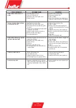
Page 16: ...low 4 Rectify the position of the combustion head control device 5 Clean or replace it The burner goes into lock out without spraying fuel Red lamp on 1 One phase missing 2 Inefficient electric motor 3 Diesel fuel not reaching the pump 4 No diesel fuel in the tank 5 Gate valve on the suction pipe closed 6 Nozzle clogged 7 Motor three phase rotates in the wrong direction see arrow 8 Bottom valve le...

Page 17: ...according to the boiler manufacturer s instructions 6 Clean them 7 Return it at the required value Defective flame flickering or protrud ing from combustion head 1 Excessive draught only when there is an ex tractor in the chimney 2 Inefficient nozzle either fouled or worn 3 Water in the fuel 4 Dirty disk 5 Excessive combustion air flow 6 Air passage between disk and blast tube ex cessively closed ...

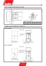
Page 18: ...NCIPLE OF AIR CONTROL WRONG ADJUSTMENT Combustion head Air passageway wide open Knobs for controlling and fastening the combustion head Air combustion inlet gate valve mostly closed Knobs for controlling and fastening the combustion head CORRECT ADJUSTMENT Air combustion inlet gate valve sensibly open Combustion head Air flow quite locked C a u t i o n Av o i d complete closure ...

Page 19: ...ection Return Pump plate Delivery nozzle 1 4 Pressure gauge connection Heating element seat Pump pressure pre setting 20 22 bar Suction 1 4 vacuum gauge connection Return Delivery nozzle 1 4 Pressuregaugeconnection Heating element seat Pump pressure pre setting 20 22 bar Pump plate ...

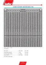
Page 20: ... 50 11 13 11 90 12 62 13 30 13 95 14 57 15 17 15 74 16 29 16 83 17 34 17 85 18 34 18 81 19 28 3 50 4 00 12 72 13 60 14 42 15 20 15 94 16 65 17 33 17 99 18 62 19 23 19 82 20 40 20 95 21 50 22 03 4 00 4 50 14 31 15 30 16 22 17 10 17 94 18 73 19 50 20 24 20 95 21 63 22 30 22 95 23 57 24 19 24 78 4 50 5 00 15 90 17 00 18 03 19 00 19 93 20 82 21 67 22 48 23 27 24 04 24 78 25 49 26 19 26 87 27 54 5 00 5...

Page 21: ...nd FLAME VALVE ACTUATING CAM 40 REFERENCE INDEX ADJUSTABLE CAMS I 2nd FLAME AIR ADJUSTING CAM 60 II TOTAL AIR CLOSURE BURNER OFF 0 III 1st FLAME AIR ADJUSTING CAM 20 IV 2nd FLAME VALVE ACTUATING CAM 40 MOTOR CONECTRON LKS 160 SETTING FOR AIR SHUTTER COMMAND IN FIRST FLAME POSITION SETTING OF MOTOR CONECTRON LKS 160 FOR AIR SHUTTER CONTROL IN SECOND FLAME POSITION ...

Page 22: ...20 22 98318_201204 WIRING DIAGRAM ...

Page 23: ...21 22 98318_201204 ...

Page 24: ...ento Fe Italy Tel 39 051 6843711 Fax 39 051 6857527 28 www baltur it info baltur it The information contained in this catalogue is not binding The manufacturer reserves the right to change the technical data and any other data it contains ...

Reviews: