background image

13 / 22

98318_201204

Assistance Service to repair the fault.

MAINTENANCE

The burners do not require particular servicing. It is good practice, 

however, to perform the following operations, at least at the end of 

the heating season:

1)  Disassemble  the  filters,  nozzle,  turbulator  disk  and  the 

ignition electrodes and clean thoroughly with solvents (petrol, 

trichloroethylene, oil). Avoid using metallic tools to clean the 

nozzle (use wood or plastic).

2)  Clean the photocell.
3)  Have the boiler cleaned and the chimney as well, if necessary.

Note: 

The nozzle or nozzles should be replaced at least every 

two heating seasons. The replacement might be required more 

frequently.

DESCRIPTION  OF  THE  TWO-STAGE 

BURNER OPERATION

The two stage burner always ignites with a limited amount of air and 

fuel (1

st

 flame) and, subsequently, after a few seconds, it will switch 

to full air and fuel operation (2

nd

 flame).

The ignition of the 2

nd

 flame is subject to the authorisation of the 

control box and control device (pressure switch or thermostat). 

When the burner works at full rate it will remain in this position until 

it reaches the pressure or temperature limit pre-set on the control 

device (pressure switch or thermostat). The control device trips, 

disconnecting the 2

nd

 flame (fuel and air), when the limit to which it 

has been pre-set is reached. Then the burner works only with the 

1

st

 flame.

Normally the 1

st

 flame alone is not sufficient to keep the temperature 

or the pressure at the required limit, and so it will decrease until it 

reaches the limit to which the control device of the 2

nd

 flame (pressure 

switch or thermostat) re-activates the total fuel and air delivery rate. 

If the burner operates only with the 1

st

 flame, it will stop completely 

when the pressure or the temperature reaches the tripping point set 

on the control device (pressure switch or thermostat). 

The burner starts up automatically again when the pressure or 

temperature falls below the limit to which the pressure switch or 

thermostat has been pre-set.

Note:

 It is normally not advisable to connect a burner working on 

a boiler for heating water for two-flame working. In this case 

the burner works (sometimes for long periods of time) with one 

flame alone, the boiler is insufficiently loaded and consequently 

the fuels come out at an extremely low temperature (lower than 

180°C) generating soot at the chimney outlet.  In addition, when 

the boiler is working at lower output than that indicated in the 

technical data, it is likely that acidic condensate and soot will 

form in the boiler, causing corrosion and clogging. When the 

two-flame burner is installed on a hot water boiler for heating 

use, it must be connected so that it works normally with both 

flames, completely stopping without passing to the first flame 

when the pre-set temperature is reached. In order for it to work 

in this way, do not install the second flame thermostat, and make 

a direct bridge connection between the equipment terminals. 

This ensures that only the capability of the burner to ignite at 

low capacity is used for a gentle ignition, which is essential for 

boilers with a pressurised combustion chamber and also very 

useful for normal boilers with depression combustion chamber. 

The ignition start/stop command is subject to the usual operating 

or safety thermostats.

Summary of Contents for BT 350 DSG

Page 1: ...BT 350 DSG ISTRUZIONI ORIGINALI IT 98318_201204 Manual user instructions TWO STAGE DIESEL BURNER ...

Page 2: ......

Page 3: ...TBML Comist GI GI Mist Minicomist PYR RiNOx Spark Sparkgas TBG TBL TBML TS IBR IB Variant LX for low NOx emissions Description forced air burners of liquid gaseous and mixed fuels for residential and industrial use meet the minimum requirements of the European Directives 2009 142 CE D A G 2004 108 CE C E M 2006 95 CE D B T 2006 42 CE D M and conform to European Standards UNI EN 676 2008 gas and co...

Page 4: ... the owner moves and leaves the equipment make sure that the booklet always goes with the equipment so it can be consulted by the new owner and or installer For all equipment with optionals or kits including electrical only origi nal accessories must be used WARNING NOTES FOR THE USER HOW TO USE THE BURNER SAFELY BURNERS This equipment must be used only for its expressly stated use applied to boil...

Page 5: ... and regulations since incorrect installation may cause damage to person animals or things for which damage the manufacturer shall not can be held responsible Before installation it is advisable to carry out careful internal cleaning of all tubing for the fuel feed system to remove any residues that could jeopardise the proper working of the burner For first start up of the equipment have qualifie...

Page 6: ...OLTAGE 3N 400 V 50 Hz STANDARD ACCESSORIES BT 350 DSG BURNER COUPLING FLANGE No 1 INSULATING GASKET No 2 STUD BOLTS No 4 M20 HEXAGONAL NUTS No 4 M20 FLAT WASHERS N 4 M 20 FLEXIBLE PIPES No 2 1 L 1500 FILTER 1 1 Combustion head 2 Insulating gasket 3 Burner coupling flange 4 Combustion head adjustment knob 5 Solenoid valves 6 Air adjustment servomotor 7 Electrical panel 8 Fan motor 9 photocell 10 Pu...

Page 7: ...5 22 98318_201204 OPERATING RANGE MOD OVERALL DIMENSIONS G A1 A2 B C D E Ø FØ E I1 L M H BT 350 DSG 1050 525 525 920 1960 350 560 360 275 440 440 400 540 M 20 365 ...

Page 8: ...erent spray angle will not cause any problems flame separation disk or combustion head fouling violent ignition etc 6 When removing the protective plastic cap from the nozzle seat be careful because if the sealing surface is indented a light scoring would be enough it will cause fuel dripping 7 Make sure that the burner head enters the combustion chamber according to the boiler manufacturer s inst...

Page 9: ...up slope towards the burner to prevent possible formation of gas bubbles Where several burners are installed in one boiler room it is essential for every burner to have its own suction pipe Only return pipes can lead to a single manifold pipe with an adequate cross section leading to the tank Never connect the return pipe directly to the suction pipe It is a good practice to properly heat insulate...

Page 10: ...turn pipe 8 Automatic fuel interception device at burner shut off 9 One way valve 10 Foot valve SUCTION FEED SYSTEM H Height difference between minimum fuel tank level and pump axis L Total length of pipeline including vertical length Subtract 0 25 mt for every bend or gate valve NOTE Comply with the regulations in force for any components missing in the pipelines PUMP AXIS PUMP AXIS PUMP AXIS H m...

Page 11: ...y ducts increases When the diesel pressure reaches 7 bar it opens the mechanical valve located in the atomiser unit Therefore the diesel reaches the first flame nozzle and and from this it enters into the combustion chamber finely atomised The pressure stabilises at a value of approx 10 bar since the first flame pressure regulator is adjusted to this value The atomised diesel comes out of the nozz...

Page 12: ...e entire burner ignition sequence When the temperature or the pressure reaches that set by the thermostat or pressure switch the burner stops The equipment resumes operation automatically as the temperature or pressure value has reduced its value by the necessary amount 1 Valve usually open 2 Valve usually open 3 Return 4 Suction 5 Foot valve 6 Pump 16 bar 7 1st flame pressure regulator 10 bar 8 A...

Page 13: ...ce freely boiler and chimney gate valves open e Make sure that the burner head penetrates into the combustion chamberaccordingtotheinstructionsoftheboilermanufacturer The burner is equipped with a coupling flange to the boiler which slides on the burner head f The nozzles fitted on the burner should be suitable for the boiler capacity replace them with others if necessary Under no circumstances sh...

Page 14: ...lator backwards degree by degree until reaching the position in which the ignition is regular and accept this new position as definitive We remind you that for the first flame is preferable to limit the quantity of air to the strictly lowest amount possible needed for safe ignition even in the most difficult circumstances CHECKS After starting up the burner check the safety devices photocell block...

Page 15: ...device of the 2nd flame pressure switch or thermostat re activates the total fuel and air delivery rate If the burner operates only with the 1st flame it will stop completely when the pressure or the temperature reaches the tripping point set on the control device pressure switch or thermostat The burner starts up automatically again when the pressure or temperature falls below the limit to which ...

Page 16: ...low 4 Rectify the position of the combustion head control device 5 Clean or replace it The burner goes into lock out without spraying fuel Red lamp on 1 One phase missing 2 Inefficient electric motor 3 Diesel fuel not reaching the pump 4 No diesel fuel in the tank 5 Gate valve on the suction pipe closed 6 Nozzle clogged 7 Motor three phase rotates in the wrong direction see arrow 8 Bottom valve le...

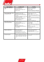
Page 17: ...according to the boiler manufacturer s instructions 6 Clean them 7 Return it at the required value Defective flame flickering or protrud ing from combustion head 1 Excessive draught only when there is an ex tractor in the chimney 2 Inefficient nozzle either fouled or worn 3 Water in the fuel 4 Dirty disk 5 Excessive combustion air flow 6 Air passage between disk and blast tube ex cessively closed ...

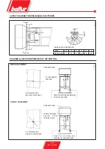
Page 18: ...NCIPLE OF AIR CONTROL WRONG ADJUSTMENT Combustion head Air passageway wide open Knobs for controlling and fastening the combustion head Air combustion inlet gate valve mostly closed Knobs for controlling and fastening the combustion head CORRECT ADJUSTMENT Air combustion inlet gate valve sensibly open Combustion head Air flow quite locked C a u t i o n Av o i d complete closure ...

Page 19: ...ection Return Pump plate Delivery nozzle 1 4 Pressure gauge connection Heating element seat Pump pressure pre setting 20 22 bar Suction 1 4 vacuum gauge connection Return Delivery nozzle 1 4 Pressuregaugeconnection Heating element seat Pump pressure pre setting 20 22 bar Pump plate ...

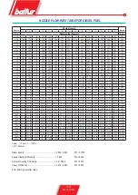
Page 20: ... 50 11 13 11 90 12 62 13 30 13 95 14 57 15 17 15 74 16 29 16 83 17 34 17 85 18 34 18 81 19 28 3 50 4 00 12 72 13 60 14 42 15 20 15 94 16 65 17 33 17 99 18 62 19 23 19 82 20 40 20 95 21 50 22 03 4 00 4 50 14 31 15 30 16 22 17 10 17 94 18 73 19 50 20 24 20 95 21 63 22 30 22 95 23 57 24 19 24 78 4 50 5 00 15 90 17 00 18 03 19 00 19 93 20 82 21 67 22 48 23 27 24 04 24 78 25 49 26 19 26 87 27 54 5 00 5...

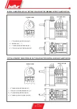
Page 21: ...nd FLAME VALVE ACTUATING CAM 40 REFERENCE INDEX ADJUSTABLE CAMS I 2nd FLAME AIR ADJUSTING CAM 60 II TOTAL AIR CLOSURE BURNER OFF 0 III 1st FLAME AIR ADJUSTING CAM 20 IV 2nd FLAME VALVE ACTUATING CAM 40 MOTOR CONECTRON LKS 160 SETTING FOR AIR SHUTTER COMMAND IN FIRST FLAME POSITION SETTING OF MOTOR CONECTRON LKS 160 FOR AIR SHUTTER CONTROL IN SECOND FLAME POSITION ...

Page 22: ...20 22 98318_201204 WIRING DIAGRAM ...

Page 23: ...21 22 98318_201204 ...

Page 24: ...ento Fe Italy Tel 39 051 6843711 Fax 39 051 6857527 28 www baltur it info baltur it The information contained in this catalogue is not binding The manufacturer reserves the right to change the technical data and any other data it contains ...

Reviews: