


1 / 10
0006160031_201307
ENGLISH
• Read carefully the instructions before starting the burner and servicing it.
• The works on the burner and on the system have to be carried out only by qualified personnel who will be responsible for observing
the
safety standards in force
.
• The system power supply must be disconnected before starting any works.
• If the works are not carried out correctly it is possible to cause dangerous accidents.
Important
WarnIng
attentIon
InformatIon
We hereby declare under our own responsibility, that our domestic and industrial
blown air burners fired by gas, oil and dual fuel series:
BPM...; BGN…; BT…; BTG…; BTL…; TBML...; Comist…; GI…; GI…Mist;
Minicomist…; PYR…; RiNOx…; Spark...; Sparkgas...; TBG...;TBL...; TS…;
IBR...; IB...
(Variant: … LX, with low NOx emissions)
respect the minimal regulation of the European Directives:
• 2009/142/EC (G.A.D)
• 2004/108/EC (E.M.C.)
• 2006/95/EC
(L.V.D)
• 2006/42/EC
(M.D.)
and have been designed and tested in accordance with the European Standards:
• EN 676 (gas and dual fuel, gas side)
• EN 267 (light oil and dual fuel, oil side)
Cento, 23 July 2013
CE0085:
DVGW CERT GmbH, Josef-Wirmer Strasse 1-3 – 53123 Bonn (D)
Statement of Conformity
CEO and General Manager
Dr. Riccardo Fava
R&D Manager
Eng. Paolo Bolognin
WARNING NOTES FOR THE USER - HOW TO USE THE BURNER SAFELY .............................................................................................................. 2
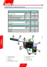
TECHNICAL SPECIFICATIONS BPM 10 EVO ............................................................................................................................................................... 3
TECHNICAL SPECIFICATIONS BPM 40 EVO ................................................................................................................................................................ 4
OPERATION DIAGRAM ................................................................................................................................................................................................... 5
GAS TRAIN DESCRIPTION FOR GAS PRESSURE ADJUSTMENT ............................................................................................................................. 5
APPARECCHIATURA DI COMANDO E CONTROLLO BRUCIATORI A GAS LME ... ..................................................................................................... 6
FAN-CONTROL ADJUSTMENT ....................................................................................................................................................................................... 8
POSITION OF ELECTRODES ......................................................................................................................................................................................... 8
IONISATION CURRENT................................................................................................................................................................................................... 8
CONVERSION FROM NATURAL GAS TO LPG .............................................................................................................................................................. 9
OPERATING ANOMALY ................................................................................................................................................................................................... 10


