


3
7
10
4
H
6
1
0002900740N3
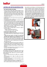
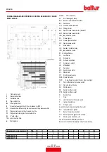
INTAKE SUPPLY SYSTEM
1 Serbatoio
3 Mesh filter
4 Pompa
6 Suction pipe
7 Return pipe
10 Foot valve
A = Pump axis
H
L = Total pipeline length including the vertical length.
TBML 90P
TBML 150P
int Ø 14 mm
int Ø 16 mm
int Ø 14 mm
int Ø 16 mm
Meters
Meters
Meters
Meters
Meters
0,5
26
45
36
55
1
22
38
30
48
1,5
19
31
25
41
2
14
25
20
32
2,5
11
19
15
24
3
-
-
10
15
3,5
-
-
4
7,5
N.B. Comply with the regulations in force for any components missing in the pipe-
lines.
H = Difference in level between minimum level in tank and pump axis
L = Deduct 0.25 m for each elbow or gate.
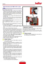
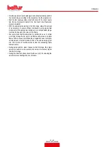
DETAILS OF PUMPS
2
3
5
4.1
7.1
6
AJ4 - AJ6
8894_1
2 Pressure gauge connector and air vent (1/8”G)
3 Pressure regulation screw:
AN...
11 - 14 bars
AJ / J... 11 - 16 bars
4 Return
4.1 Return with inner by-pass dowel
5 Suction
6 Delivery to nozzle
7 Vacuum gauge connector (1/8”G)
7.1 Vacuum gauge connector and internal by-pass dowel
CAUTION / WARNINGS
The pump is preset at a pressure of 12 bar
0002900331
2
4.1
5
2
6
3
6
7
AN 47 - 57 - 67 - 77 - 97
ENGLISH
18 / 42
0006160079_202008
Summary of Contents for 56510010
Page 2: ......
Page 42: ...SCHEMI ELETTRICI ITALIANO 40 42 0006160079_202008...
Page 44: ...ITALIANO 42 42 0006160079_202008...
Page 84: ...WIRING DIAGRAMS ENGLISH 40 42 0006160079_202008...
Page 86: ...ENGLISH 42 42 0006160079_202008...
Page 87: ......