


19
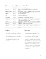
7. Maintenance Items for Bally Northwind Blast Chillers
7.1 Maintenance Points
•
Probe plugs
The temperature probes are low voltage
circuits that are routed through plugs at the
top of the coil frame and behind the fan frame.
If you start getting erroneous probe readings,
use a light abrasive pad (like Scotch-Brite) to
clean the plugs and a Q-tip to clean the
receptacles.
•
Defrost Switch
The defrost switch sends a signal back to the
controller indicating the temperature of the
coil. The switch is designed to handle high
amperages and has a life span of about
100,000 cycles. If the switch “fails closed”, you
will not be able to go into defrost, even when
the coil is frozen solid. If it “fails open”, it will go
into defrost every time (even when the blast
chiller interior is at room temperature) and stay
in defrost the full 20 minutes. See the above
information to replace it if you experience
either situation.
Item
Bally PN Location/Means of Access
Fan Motor
016915
Inside Fan Frame/Remove entire Fan Cover (not the wire fan
guards).
Refrigeration Valve
005424
Part of liquid line, left side of Coil Frame. Remove coil filter and side
cover with 6 black topped screws.
Solenoid
061514
Attached to valve, above.
TXV
000388
Part of Liquid line, see above.
Power Head
099644
Attached to TXV, above (special 60” bulb tube).
Defrost Switch
088779
In the coil frame, top bend, usually on same side as the liquid line.
Wired closely to the coil junction box.
Air Probe
046759
Behind the upper fan motor/ Remove the Fan Cover (not the Wire
Fan guard).
Food Probe
089226
In plain sight. Plugged into top of coil frame.
Light Bulb
none
In plenum. / Unscrew 4 flat head screws with a 2.5mm hex key (not
a common size). Hex key is taped to the light at the time of
shipment.


