background image

www.balluff.com

9

deutsch

4.2 

Funktion

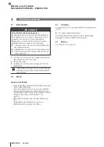
Die IO-Link-Hubs verfügen über acht Eingangs-Ports mit 

insgesamt 16 Eingängen. Die Anbindung an die überge-

ordnete Masterbaugruppe erfolgt über das IO-Link-Proto-

koll.
Funktional ist das Hub-Modul vergleichbar mit einer passi-

ven Verteilbox: Aufnahme von digitalen Signalen und 

Weitergabe über die IO-Link-Schnittstelle.

4.3 

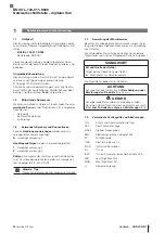
Anzeigeelemente

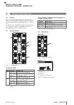
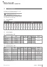
Bild 4-3: 

LED 1

LED 0

IOL

U

S

Anzeigeelemente

Modulstatus-LEDs

LED Anzeige

Bedeutung

U

S

Grün statisch Spannung im Nennbereich
Grün, schnell 

blinkend

Betriebsspannung des Geräts ist 

zu niedrig (< 18 V).

Aus

Modul ist ohne Spannung

IOL

Grün, nega-

tiv gepulst

IO-Link-Kommunikation ist aktiv. 

Das Gerät ist bereit.

Grün statisch Keine Kommunikation
Aus

Modul ist ohne Spannung

Tab. 4-1:  Status-LEDs

4


Produktbeschreibung (Fortsetzung)

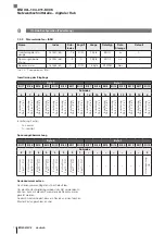
LEDs der digitalen Eingänge (LED 0, Eingang Pin 4 

und LED 1, Eingang Pin 2)

Anzeige

Bedeutung

Gelb statisch Eingangssignal = 1
Rot statisch

Kurzschluss der Sensorversorgung

Aus

Eingangssignal = 0

Tab. 4-2:  LEDs der digitalen Eingänge

4.4 

Bedruckung

Frontseitig

Bild 4-4: 

Typ

Bedruckung frontseitig

Seitlich

1)

2)

3)

4)

1

 Hardwareversion

2)

 Softwareversion

3)

 Bestellcode

4)

 Fertigungsdatum und Ländercode

Bild 4-5:  Bedruckung seitlich (Beispiel)

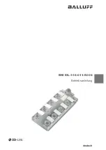
BNI IOL-104-011-K006

Netzwerkschnittstelle – digitaler Hub

Summary of Contents for BNI IOL-104-011-K006

Page 1: ...BNI IOL 104 011 K006 deutsch Betriebsanleitung english User s Guide...

Page 2: ...www balluff com...

Page 3: ...BNI IOL 104 011 K006 Betriebsanleitung deutsch...

Page 4: ...www balluff com...

Page 5: ...geelemente 9 4 4 Bedruckung 9 5 Einbau und Anschluss 10 5 1 Einbau 10 5 2 Elektrischer Anschluss 10 5 2 1 Spannungsversorgung 10 5 2 2 IO Link Schnittstelle 10 5 2 3 Digitaler Eingangs Port 10 5 3 Sch...

Page 6: ...ntsorgung 17 10 Technische Daten 18 10 1 Umgebungsbedingungen 18 10 2 Elektrische Merkmale 18 10 3 Elektrischer Anschluss 18 10 4 Schnittstelle 18 10 5 Material 18 10 6 Mechanische Merkmale 18 10 7 Zu...

Page 7: ...chnung sind Dezimalzahlen z B 23 Hexadezimale Zahlen werden mit vorangestell tem 0x dargestellt z B 0x12AB Hinweis Tipp Dieses Symbol kennzeichnet allgemeine Hinweise 1 4 Bedeutung der Warnhinweise Be...

Page 8: ...h 2 3 Allgemeine Sicherheitshinweise T tigkeiten wie Einbau Anschluss und Inbetriebnahme d rfen nur durch geschulte Fachkr fte erfolgen Eine geschulte Fachkraft ist wer aufgrund seiner fachli chen Aus...

Page 9: ...lb getrennt zu bestellen Empfohlenes Zubeh r finden Sie unter www balluff com auf der Produktseite 3 2 Transport Produkt in Originalverpackung bis zum Verwendungs ort transportieren 3 3 Lagerbedingung...

Page 10: ...Eingangs Port 1 4 Standard Eingangs Port 3 5 Status LED 1 Eingang Pin 2 6 Standard Eingangs Port 5 7 Status LED 0 Eingang Pin 4 8 Status LED Versorgung Sensoren US 9 Standard Eingangs Port 7 10 Stand...

Page 11: ...des Ger ts ist zu niedrig 18 V Aus Modul ist ohne Spannung IOL Gr n nega tiv gepulst IO Link Kommunikation ist aktiv Das Ger t ist bereit Gr n statisch Keine Kommunikation Aus Modul ist ohne Spannung...

Page 12: ...er falsche Polarit t der Anschl sse kann zu Funktionsverlust oder einer Besch digung des Produkts f hren Ma nahmen treffen um einen fehlerhaften Anschluss oder eine Verpolung zu verhindern Herumhantie...

Page 13: ...an den bergeordneten IO Link Master erfolgt mit einem Standard Sensorkabel Die Anbindung von digitalen Sensoren an den beschriebe nen Hub erfolgt mit standardisierten ungeschirmten Sensorkabeln Kabel...

Page 14: ...dere nach dem Austausch des BNI oder der Reparatur durch den Hersteller die korrekten Werte pr fen 6 2 Betrieb Hinweise zum Betrieb Funktion des BNI und aller damit verbundenen Kompo nenten regelm ig...

Page 15: ...ikationsdaten DPP Name Index Zugriff L nge Datentyp Data Storage Default Vendor Name 0x0007 7 R 2 Byte STRING n a 0x0378 Vendor Text 0x0008 8 R STRING n a Product Name 0x0009 9 R 3 Byte STRING n a 0x0...

Page 16: ...nvertierung Port 5 Pin 2 Invertierung Port 4 Pin 2 Invertierung Port 3 Pin 2 Invertierung Port 2 Pin 2 Invertierung Port 1 Pin 2 Invertierung Port 0 Pin 2 Invertierung Port x 0 normal 1 invertiert Spa...

Page 17: ...8023 Access denied 0x8033 Parameter length overrun 0x8034 Parameter length underrun 0x8035 Function not available Tab 7 4 Fehlercodes 7 4 Events Event Code Beschreibung 0x5111 Low sensor voltage US 0x...

Page 18: ...bertragen wodurch minimale Ausfallzeiten garantiert werden Um die Datenhaltung zu verwenden muss die Validierung eingeschaltet werden Informationen zu der Konfigurierung der Datenhaltung und Validier...

Page 19: ...ie Kontakt mit unserem Service Center auf 9 2 Demontage Ger t nur in spannungsfreiem Zustand demontieren 9 3 Entsorgung Befolgen Sie die nationalen Vorschriften zur Entsor gung Weitere Informationen f...

Page 20: ...Buchse 10 4 Schnittstelle IO Link Version 1 1 Daten bertragungsrate COM2 38 4 kBit s Minimale Zykluszeit 3 5 ms Prozessdatenl nge 2 Byte Eingang 10 5 Material Geh usematerial Kunststoff transparent 1...

Page 21: ...BNI IOL 104 011 K006 User s Guide english...

Page 22: ...www balluff com...

Page 23: ...4 4 Labeling 9 5 Installation and connection 10 5 1 Installation 10 5 2 Electrical connection 10 5 2 1 Power supply 10 5 2 2 IO Link interface 10 5 2 3 Digital input port 10 5 3 Shielding and cable r...

Page 24: ...mbly 17 9 3 Disposal 17 10 Technical data 18 10 1 Ambient conditions 18 10 2 Electrical data 18 10 3 Electrical connection 18 10 4 Interface 18 10 5 Materials 18 10 6 Mechanical features 18 10 7 Appro...

Page 25: ...icated are decimals e g 23 Hexadecimal numbers are represented with a preceding 0x e g 0x12AB Note tip This symbol indicates general notes 1 4 Explanation of the warnings Always observe the warnings i...

Page 26: ...s 2 3 General safety notes Activities such as installation connection and startup may only be carried out by qualified personnel Qualified personnel are persons whose technical trai ning knowledge and...

Page 27: ...y and must be ordered separately Recommended accessories can be found at www balluff com on the product page 3 2 Transport Transport product to location of use in original packaging 3 3 Storage condit...

Page 28: ...Link interface 3 Standard input port 1 4 Standard input port 3 5 Status LED 1 Input Pin 2 6 Standard input port 5 7 Status LED 0 Input Pin 4 8 Status LED Sensor supply US 9 Standard input port 7 10 S...

Page 29: ...ating voltage of the device is too low 18 V Off Module without supply voltage IOL Green negative pulsing IO Link communication is active The device is ready Green static No communication Off Module wi...

Page 30: ...onnection or polarity of the connections can cause a loss of function or damage to the product Take measures to prevent incorrect connection or reverse polarity Prevent tampering at the connections Ne...

Page 31: ...ing The connection to the higher level IO Link master is made with a standard sensor cable Digital sensors are connected to the described hub using standardized unshielded sensor cables Cable length T...

Page 32: ...for the correct values especially after replacing the BNI or after repair by the manufac turer 6 2 Operation Operating notes Regularly check function of the BNI and all associated components Depending...

Page 33: ...PP Name Index Access Length Data Type Data Storage Default Vendor Name 0x0007 7 R 2 bytes STRING n a 0x0378 Vendor text 0x0008 8 R STRING n a Product Name 0x0009 9 R 3 bytes STRING n a 0x050112 Produc...

Page 34: ...n 2 Inversion Port 5 Pin 2 Inversion Port 4 Pin 2 Inversion Port 3 Pin 2 Inversion Port 2 Pin 2 Inversion Port 1 Pin 2 Inversion Port 0 Pin 2 Inversion Port x 0 normal 1 inverted Voltage monitoring By...

Page 35: ...e 0x8023 Access denied 0x8033 Parameter length overrun 0x8034 Parameter length underrun 0x8035 Function not available Tab 7 4 Error codes 7 4 Events Event Code Description 0x5111 Low sensor voltage US...

Page 36: ...sferred to the new device thus guaranteeing minimum downtimes In order to use the data storage the validation must be switched on Information about the configuration of the data storage and validation...

Page 37: ...ive contact our Service Center 9 2 Disassembly Only disassemble the device when it is de energized 9 3 Disposal Observe the national regulations for disposal Additional information can be found at www...

Page 38: ...8 M12 A coded 4 pin socket 10 4 Interface IO Link version 1 1 Data transmission rate COM2 38 4 kBit s Minimum cycle time 3 5 ms Process data length 2 bytes input 10 5 Materials Housing material Plasti...

Page 39: ......

Page 40: ...hengshan Rd 8F Building A Yunding International Commercial Plaza 200125 Pudong Shanghai Phone 86 400 820 0016 Fax 86 400 920 2622 service cn balluff com cn DACH Service Center Germany Balluff GmbH Sch...

Reviews: