background image


www.balluff.com 


2


Safety 

2.1.


Intended use 

  This  guide  describes  the  Balluff  Network  Interface  BNI  IOL-

……  for  the  application  as 

peripheral output module to establish connection of binary actuators. Hereby it is about an 
IO-Link device which communicates by means of IO-Link protocol with the superordinate 
IO-Link master assembly. 


2.2.


Installation and 
startup 


Note 

Installation and startup are to be performed only by trained specialists. Qualified 
personnel are persons who are familiar with the installation and operation of the 
product, and who fulfills the qualifications required for this activity. Any damage 
resulting from unauthorized manipulation or improper use voids the anufacturer's 
guarantee and warranty. The Operator is responsible for ensuring that 
applicable of safety and accident prevention regulations are complied with. 


2.3.


General safety 
instructions 


Commissioning and inspection 

Before commissioning, carefully read the operating manual. 
The system must not be used in applications in which the safety of persons is dependent on 
the function of the device. 

Authorized Personnel 

Installation and commissioning may only be performed by trained specialist personnel. 

Intended use 

Warranty and liability claims against the manufacturer are rendered void by: 


Unauthorized tampering 


Improper use 


Use, installation or handling contrary to the instructions provided in this operating 

manual 

Obligations of the Operating Company 

The device is a piece of equipment from EMC Class A. Such equipment may generate RF 
noise. The operator must take appropriate precautionary measures. The device may only be 
used with an approved power supply. Only approved cables may be used. 

Malfunctions 

In the event of defects and device malfunctions that cannot be rectified, the device must be 
taken out of operation and protected against unauthorized use. 
Intended use is ensured only when the housing is fully installed. 


Hazardous 
voltage 


Note 

Disconnect all power before servicing equipment. 


Note 

In the interest of product improvement, the Balluff GmbH reserves the right to 
change the specifications of the product and the contents of this manual at any 
time without notice. 


Summary of Contents for BNI IOL-102-000-Z012

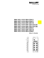
Page 1: ...BNI IOL 102 000 Z012 BNI IOL 104 000 Z012 BNI IOL 104 S01 Z012 BNI IOL 104 S01 Z012 C01 BNI IOL 104 S01 Z012 C02 BNI IOL 302 000 Z012 BNI IOL 302 S01 Z012 BNI IOL 302 000 Z042 User s Guide...

Page 2: ...Module versions 5 3 4 Sensor Interface 6 4 IO Link Interface 7 4 1 IO Link Data 7 4 2 Prozess data Input data 9 4 3 Prozess data Output data 13 Parameter data Request data 14 Inversion of the inputs...

Page 3: ...phical Conventions The following typographical conventions are used in this guide Enumerations Enumerations are shown in list form with bullet points Entry 1 Entry 2 Actions Action instructions are in...

Page 4: ...ed in applications in which the safety of persons is dependent on the function of the device Authorized Personnel Installation and commissioning may only be performed by trained specialist personnel I...

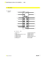
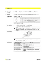
Page 5: ...tus LED Communication module 4 Standard I O port 1 5 Standard I O port 3 6 Standard I O port 5 7 Standard I O port 7 8 Mounting hole 9 Pin Port LED Signalstatus 10 Standard I O port 6 11 Standard I O...

Page 6: ...O Link line to the sensor hub Note For BNI IOL 10x xxx Z012 a standard 3 wire sensor cable is used for connection to the host IO Link master For BNI IOL 302 xxx Z0xx a 4 wire sensor cable is necesarry...

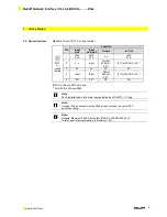
Page 7: ...n c Input Output 500 mA 2A In Out 500 mA 2A 3 0V 0V 0V 0V 4 Input Input Ouput 500 mA 2A In Out 500 mA 2A 5 FE FE FE FE BNI IOL 106 xxx Z012 not used For BNI IOL 302 xxx Z042 Note For the digital input...

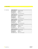
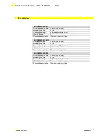
Page 8: ...time 3 ms minimal cycle time BNI IOL 104 S01 Z012 Data transmission rate COM2 38 4 kBaud Minimal cycle time 3 ms Process data length 4 Byte input IO Link Revision 1 0 Process data cycle time 12 ms min...

Page 9: ...cess data cycle time 12 ms minimal cycle time BNI IOL 302 S01 Z012 bertragungsrate COM2 38 4 kBaud Minimal cycle time 3 ms Process data length 8 Byte input 2 Byte output IO Link Revision 1 0 Process d...

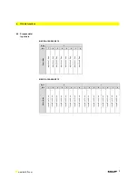
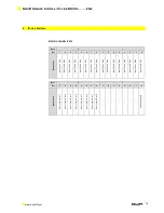
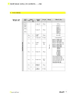
Page 10: ...t 2 Pin 4 Input Port 1 Pin 4 Input Port 0 Pin 4 BNI IOL 104 000 Z012 Byte 0 1 Bit 7 6 5 4 3 2 1 0 7 6 5 4 3 2 1 0 Description Input Port 7 Pin 4 Input Port 6 Pin 4 Input Port 5 Pin 4 Input Port 4 Pin...

Page 11: ...in 4 Input Port 2 Pin 4 Input Port 1 Pin 4 Input Port 0 Pin 4 Input Port 7 Pin 2 Input Port 6 Pin 2 Input Port 5 Pin 2 Input Port 4 Pin 2 Input Port 3 Pin 2 Input Port 2 Pin 2 Input Port 1 Pin 2 Input...

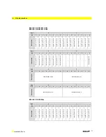
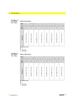
Page 12: ...cuit Port 6 Short circuit Port 5 Short circuit Port 4 Short circuit Port 3 Short circuit Port 2 Short circuit Port 1 Short circuit Port 0 Undervoltage US Byte 4 5 Bit 7 6 5 4 3 2 1 0 7 6 5 4 3 2 1 0 D...

Page 13: ...5 Bit 7 6 5 4 3 2 1 0 7 6 5 4 3 2 1 0 Description Short Circuit Port 7 Pin 4 Short Circuit Port 6 Pin 4 Short Circuit Port 5 Pin 4 Short Circuit Port 4 Pin 4 Short Circuit Port 3 Pin 4 Short Circuit...

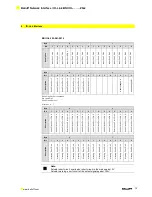
Page 14: ...6 Pin 4 Output Port 5 Pin 4 Output Port 4 Pin 4 Output Port 3 Pin 4 Output Port 2 Pin 4 Output Port 1 Pin 4 Output Port 0 Pin 4 Output Port 7 Pin 2 Output Port 6 Pin 2 Output Port 5 Pin 2 Output Port...

Page 15: ...yte www balluff com 12hex 0 Product name 20 24 Byte BNI IOL 102 000 Z012 BNI IOL 104 000 Z012 BNI IOL 104 S01 Z012 BNI IOL 104 S01 Z012 C01 BNI IOL 104 S01 Z012 C02 BNI IOL 302 000 Z012 BNI IOL 302 S0...

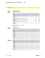
Page 16: ...e Pin4 2 Byte 0hex FFFFhex 0000hex 43hex 0 1 8 Fault State Pin2 2 Byte 0hex FFFFhex 0000hex 44hex 0 1 16 Sp Monitoring 2 Byte 0hex FFFFhex 45hex 0 1 16 Actuator short 2 Byte 0hex FFFFhex 46hex 0 1 16...

Page 17: ...Inversion Port 5 Pin 2 Inversion Port 4 Pin 2 Inversion Port 3 Pin 2 Inversion Port 2 Pin 2 Inversion Port 1 Pin 2 Inversion Port 0 Pin 2 Inversion Port x 0 Normal 1 Inverted Port Direction 41hex BNI...

Page 18: ...ort 6 Pin 4 Fault State Port 5 Pin 4 Fault State Port 4 Pin 4 Fault State Port x 00 0 01 1 10 Last state 11 Not defined Fault State of the outputs Pin 2 43hex BNI IOL 302 xxx Z0xx Byte 0 1 Bit 7 6 5 4...

Page 19: ...Short circuit Port 7 Pin 4 Short circuit Port 6 Pin 4 Short circuit Port 5 Pin 4 Short circuit Port 4 Pin 4 Short circuit Port 3 Pin 4 Short circuit Port 2 Pin 4 Short circuit Port 1 Pin 4 Short circu...

Page 20: ...case of BNI IOL 104 S01 Z012 C01 and BNI IOL 104 S01 Z012 C02 Only in case of BNI IOL 104 S01 Z012 C02 4 4 Errors Error Code Description 0x8011 Index not available 0x8012 Subindex not available 0x803...

Page 21: ...ly when plugged in and threaded in Weight ca 500 g Dimensions B H T in mm 68 x 181 5 x 31 8 5 3 Electrical Data Operating conditions 18 30 2 V DC per EN 61131 2 Ripple 1 Current draw without load 90 m...

Page 22: ...Indicator Function LED 1 Green Red Supply Module ok Undervoltage LED 3 Green Red Supply actuators ok Undervoltage LED 6 Green Green flashing Communication error communication ok LED I O Ports Indicato...

Page 23: ...5 poles Z042 Die cast zinc housing matte nickel plated Bus connection and power supply 1xM12 external thread IO Ports 8xM12 female 5 poles 2A Outputs Special functions C01 Identification 2 Byte C02 Id...

Page 24: ...ff com www balluff com Balluff GmbH Schurwaldstrasse 9 73765 Neuhausen a d F Germany Tel 49 7158 173 0 Fax 49 7158 5010 balluff balluff de Nr 892931 E Edition 1404 Replaces Edition 1210 Subject to mod...

Reviews: