background image


4.


Pellet stove components 

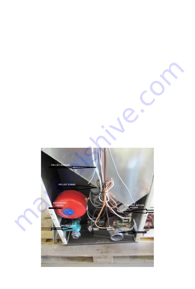
The pellet stove consists of the following components

-


combustion chamber – 

fig. 3; 

-


pot - place where the pellets burn 

– fig. 4 and fig. 5; 

-


water heater; 

-


pellet hopper – 

pellets for burning are filled into it – fig. 1 and fig.2; 

-


auger for pellets (screw auger)– 

delivers pellets from the hopper to the inclined 

channel and from there to the pot for combustion – fig. 1; 

-


electric gear motor: 

drives the pellet auger (screw auger)– fig. 1; 

   - electric lighter: 

for initial ignition of the pellets in the pot; 

-


smoke extractor: 

ensures removal of flue gases from the combustion chamber to the 

flue and sucks in air for combustion fig. 1, 

   - pressure switch: 

reports the underpressure in the exhaust tract; 

-


limiting thermostat (STB): 

in the event of a failure in the controller or the sensor 

for measuring the temperature of the hot water, to turn off the supply of pellets; 

-


thermal limiter mounted on the inclined chute for feeding pellets into the 

combustion chamber: 

shuts down the pellet auger in case of backfire or if the inclined 

chute temperature is exceeded. 

-


light detector: 

Opto-sensor for monitoring the light intensity of the flame 

determining the presence of combustion. 

-


electronic controller with control panel: 

monitors and manages the 

combustion process as well as ensures the operation of the provided protections-

fig.1 


Fig. 1 

Summary of Contents for Sofia

Page 1: ...1 INSTALLATION OPERATION AND MAINTENANCE INSTRUCTIONS...

Page 2: ...tove be sure to read this manual This instruction has been prepared in accordance with the laws and regulations for safety in the installation and operation of pellet stoves Failure to follow the inst...

Page 3: ...ed with a working zero conductor 13 Switch off the stove in case of damage or malfunction 14 Unburned pellets collected in the burner after each failed ignition attempt must be removed before starting...

Page 4: ...mbustion chamber to the flue and sucks in air for combustion fig 1 pressure switch reports the underpressure in the exhaust tract limiting thermostat STB in the event of a failure in the controller or...

Page 5: ...5 Fig 2 Fig 3...

Page 6: ...6 Fig 4 Burner pot Fig 5 Burner pot...

Page 7: ...allation to check the exhaust gas emissions after the installation and adjustment of the pellet stove to instruct the user how to adjust operate and clean the pellet stove 6 Installation of the pellet...

Page 8: ...h wind protection device The pipe system must be airtight insulated with materials resistant to high temperatures heat resistant silicone Classic masonry chimneys can be used to vent the smoke If the...

Page 9: ...4 Connecting the pellet stove to the power supply The pellet stove works with a supply voltage of 230 V 50 Hz and therefore it must be connected to an electrical supply Before connecting the pellet s...

Page 10: ...ll parameters and perform the first ignition In most cases the pellet stove is set by the manufacturer but the installer must check these settings and make adjustments for the pellets the user is usin...

Page 11: ...the pellet stove It is recommended that the burner pot ashtray and ashtray niche be cleaned after each use every day The burner pot can be cleaned during operation of the pellet stove by a cleaning m...

Page 12: ...12 Fig 9 Fig 10...

Page 13: ...it as required 5 Radiators The pellet stove is equipped by the manufacturer with a water pump and expansion tank as well as with a deaerator The installer must install a safety valve in the water heat...

Page 14: ...on efficiency is also determined by the low moisture content in pellets constantly below 10 compared to 20 to 30 moisture content of sawn wood Pellet bags can be stored in a small area in a dry garage...

Reviews: