BVRDTSM Touchscreen Microphone
Installation Instructions
20
BVRDTSM Touchscreen Microphone issue 1
3.2 O
PERATION
3.2.1 User Accounts
The BVRDTSM can be configured with multiple user accounts
with different functions allowed in different accounts.
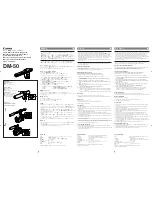
ID
Function
Description
E
Fault Accept / Lamp Test
Used to silence the Fault Buzzer and to test the LED
indicators
F
Emergency Key Switch
Turn to enable high priority emergency broadcast and
enable broadcast of BVRD2M/4 stored VA messages
G
NFC Antenna Aerial
Present NFC card to this area to log on
H
Status LED’s
Power On: Power supplied to BVRDTSM
Healthy: Indicates healthy status
General Fault: Indicates general fault with BVRDTSM
microphone or connected BVRD2M/M4 router
System Fault: Indicates CPU Fault, Reboot or
Configuration Data Corruption
VA Active: Indicates and emergency broadcast is being
made on the system.
I
PTT Button
Press and hold to broadcast to selected zones*
J
Scroll Buttons
Used to scroll between zone pages if more than 8 zones
configured
K
Speech Level Indicator
Display current audio level of broadcast
L
Speak Now Indicator
Indicates when a pre-announcement chime has finished
playing
M
Emergency Mode Indicator Indicates that the BVRDTSM is currently in Emergency
Mode
N
Menu Bar
Used to select different configured functions including:
Zones: Zone Status Display
Groups: Group Selection
VA Messages: Router stored emergency message
playback
Music: Background Music routing
Volume: Volume Controls
PA Messages: BVRDTSM stored non-emergency
message playback
Logs: Fault Log Display