background image

3

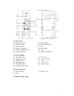
D1: Transmission Indication LED            D2: Wall Mount Hole
D3:  Battery  Compartment                                   D4:  “RESET”  button
D5:  Channel  Select  Switch                                   D6:  Stand

4.Getting Started:
4.1 Main Unit:

Slide open main unit battery compartment cover [C2]
 Insert 3 x AA batteries observing polarity [ “+” and“ –“ marks]
 Replace main unit battery compartment cover [C2]
 Use a pin to press the RESET [B10] button on the rear of the main unit, the main unit is

now ready for use

4.2 Outdoor Thermo Sensor

Batteries  compartment  (D3)  of  thermo  sensor  is  locating  behind  the  back  cover,
unscrews the batteries cover to open.

Insert 2 x AAA batteries observing polarity [ “+” and “–“ marks]

5. Installation

5.1 Main Unit

The main unit can be placed onto any flat surface (C3), or wall mounted by the hanging
hole (C1) at the back of the unit.

5.2 Outdoor Thermo sensor

The remote sensor should be securely mounted onto a horizontal surface.

Note:

Transmissions between receiver and transmitter can reach up to 30m in open

area.   Open Area: there are no interfering obstacles such as buildings, trees, vehicles,
high voltage lines, etc.

6. Weather Forecast Function
6.1 Operation

Summary of Contents for 865991

Page 1: ...99 Day of week in 8 languages user selectable 1 3 Humidity Measurable range 20 99 Max Min Memory 1 4 Temperature Indoor measurable range 0 50 C 32 122 F Measures C F user selectable Outdoor measurable range 20 50 C 4 122 F Max Min Memory indoor outdoor Comfort Indicator Bar 1 5 Outdoor Sensor Low battery indicator for Outdoor Thermo Sensor Wall Mount or Table Stand One Wireless Thermo Sensor Inclu...

Page 2: ...midity A8 Comfort Indicator Bar A9 Date A10 Moon Phase A11 Time A12 Radio Controlled Icon 2 2 Part B Buttons B1 WEATHER button B2 AL ON OFF button B3 MODE button B4 CHANNEL button B5 MAX MIN button B6 SNOOZE LIGHT button B7 C F button B8 12 24 button B9 button B10 RESET button 2 3 Part C Structure C1 Wall Mount Hole C2 Battery Cover C3 Stand 3 Outdoor Thermo Sensor ...

Page 3: ... Batteries compartment D3 of thermo sensor is locating behind the back cover unscrews the batteries cover to open Insert 2 x AAA batteries observing polarity and marks 5 Installation 5 1 Main Unit The main unit can be placed onto any flat surface C3 or wall mounted by the hanging hole C1 at the back of the unit 5 2 Outdoor Thermo sensor The remote sensor should be securely mounted onto a horizonta...

Page 4: ...after the current weather status is entered 6 2 Weather Conditions There are totally 5 different weather status animations in the weather forecast Note is shown if the weather forecast is Rainy and outdoor temperature any channel under 0 C Frost Alert is shown if the outdoor temperature any channel is between 2 C 3 C If there is any inconsistency of weather forecast between Local Weather Station a...

Page 5: ...o sensor If main unit failed to receive transmission from outdoor thermo sensor in first 3 minutes after the batteries inserted display on the LCD hold Channel button B4 for 3 seconds to receive transmission manually RF icon flashes on the LCD Note Buttons except Channel B4 Light B6 buttons will not function while scanning for thermo sensor s signal unless they are well received or stopped manuall...

Page 6: ...y is shown on the LCD Hold MAX MIN button B5 for 3 seconds to clear the recorded maximum and minimum reading 5 Comfort Indicator Bar A16 for the display of pleasant unpleasant climate 6 The use of 1 5m cord Temperature Probe Insert the probe plug D6 to the jack on the right hand side of the Thermo Sensor Unit Put the cable outside and leave the Thermo Sensor Unit indoor to avoid freezing up the ba...

Page 7: ...8 2 Manual Time Setting Hold MODE button B3 for 3 seconds to enter Clock Calendar setting mode Press B9 or B8 button to adjust the setting and press MODE button B3 to confirm each setting The setting sequence is shown as follow Hour Minute Second Year Month Day Time Zone Day of week language 8 languages can be selected in Day of week they are German French Spanish Italian Dutch Denmark Russian and...

Page 8: ...tting Press B9 or B8 button to adjust the alarm time Press MODE button B3 to confirm the setting Press AL ON OFF button B2 to switch alarm on or off If it is on shown on the LCD When Alarming press SNOOZE LIGHT button B6 to activate the snooze alarm flash on the LCD The alarm will snooze for 5 minutes then it alarms again This snooze function can be enabled for maximum 7 times 8 5 Dual Time Settin...

Page 9: ...sensor must not be set up and installed under water Set it up in away direct sunlight and Rain Never clean the device using abrasive or corrosive materials or products Abrasive cleaning agents may scratch plastic parts and corrode electronic circuits If there is any inconsistency of weather forecast between Local Weather Station and this unit the Local Weather Station s forecast should prevail The...

Page 10: ... at a specially designated place such as your municipal domestic chemical waste depot Never throw empty batteries away but deposit them in special battery boxes or hand them in as domestic chemical waste at your municipal depot DECLARATION OF CONFORMITY Herewith we declare that this wireless transmission device does comply with the essentials requirements of R TTE Directive 1999 5 EC A copy of the...

Reviews: