background image

Masoneilan 35002 Series Camflex II Instruction Manual  |  10

Copyright 2020 Baker Hughes Company. All rights reserved.

D.


Slide  the  valve  shaft  partly  into  the  lower  yoke  opening, 

allowing enough room to place packing flange (14) over the 

shaft (19). 


 Note: Packing flange (14) is placed on the shaft (19) 

with the concave side toward the valve packing (17).

E.


Ensure  slots  in  packing  flange  (14)  line  up  with  packing 

flange studs (13).

F.


With packing flange on the shaft, continue sliding the valve 

shaft toward the yoke (33) and through the grommet (12) in 

the yoke (33).

G.


Place the lever (34) in the yoke and in line with the shaft so 

the boss on one side of the lever shaft hole is toward the 

shaft bearing (8) and engage the shaft to the lever splines. 


 Note: Shaft must engage lever so the indicator dot on 

the clevis pin, when placed in the lever hole, shows the 

valve closed. Temporarily place clevis pin into lever 

(34) and check indicator dot alignment. Dot should just 

start touching the closed indicator line on the front 

cover (32) (Refer to Figure 18). If the orientation is not 

changed, align lever and mark on yoke then check 

alignment. (Refer to Figure 17). 

Do not use air pressure to check alignment, since 

during normal operation and with full air pressure, 

the Indicator may overshoot the closed Indicator 

mark on the cover. This is acceptable.

H.


Slide shaft completely through lever to engage shaft bearing 

(8). Yoke should now be fully seated on the valve bonnet 

flange.

I.


Replace and tighten body stud nuts (27).

J.


Replace  packing  flange  stud  nuts  (94)  and  finger  tighten 

only.

K.


Slide the lever (34) on the shaft (19) toward the valve and 

tighten lever capscrew (49).

L.


Pull the lever and shaft toward the bearing (8) in the yoke.

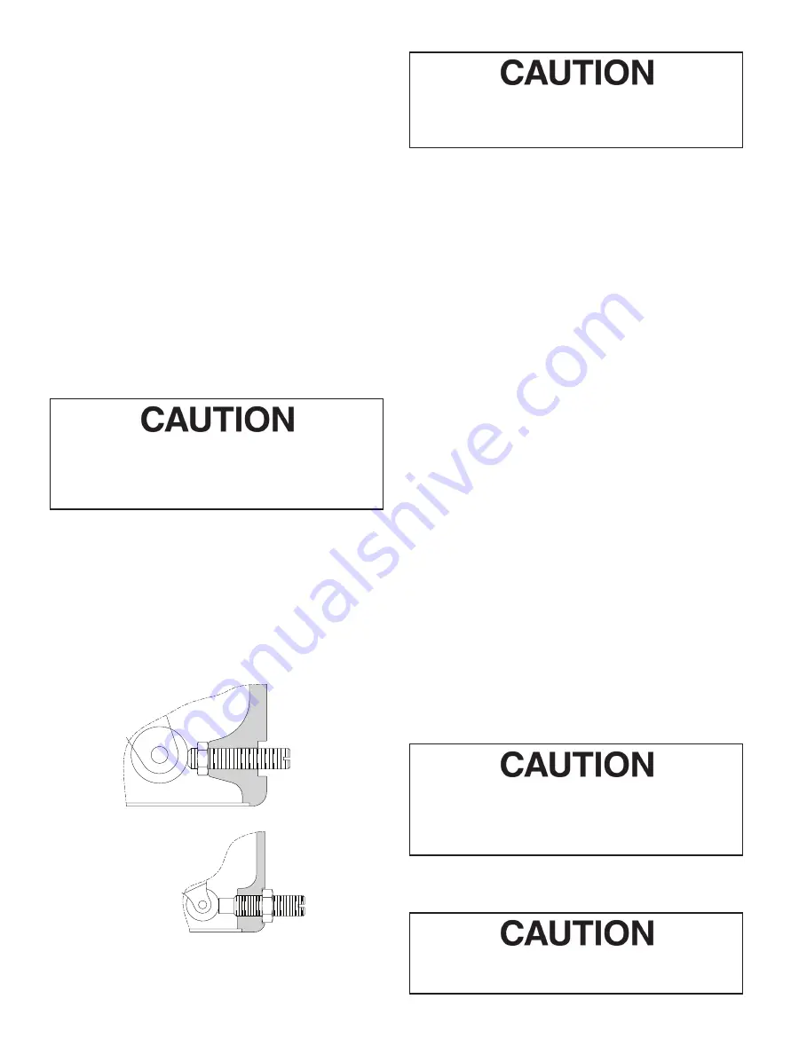
LIMIT STOP STD CAMFLEX 6" and 7"

LIMIT STOP STD CAMFLEX 4.5"

Figure 9

This is required to ensure the shaft (19) is shouldered 

on the shaft bearing (8) and to ensure free operation 

of the valve.

M.


Loosen  lever  capscrew  (49)  and  slide  lever  (34)  so  it  will 

shoulder against the shaft bearing (8) and tighten capscrew 

(49). 


 Note: if the actuator cylinder (38) has been removed 

proceed to step N. If it has not, proceed to Section 11, 

Actuator Stem Adjustment. 

N.


Determine the desired actuator action and replace actuator 

cylinder (38) on the yoke (33) and secure in place with four 

capscrews (36) and lockwashers (37).

O.


Proceed to Section 11, Actuator Stem Adjustment. 

10.3 Handwheel Reassembly 

A.


Place the valve so the position cover (11) is up.

B.


Remove Truac ring (50) and handwheel washer (51) from 

the handwheel powerscrew.

C.


Insert handwheel powerscrew with lock (52) in place into the 

appropriate hole in the yoke and screw in clockwise. 

D.


Replace the washer (51) and Truac ring (50)

E.


Back off handwheel lightly against washer and lock in the off 

position with lock (52).

F.


Replace bottom cover (11) by snapping in place. 


 Note: To use the handwheel, loosen the lock (52) and 

turn. The handwheel can be used as a limit stop on the 

valve by locking it in any position. 

10.4 Limit Stop Reassembly

Two different types of assembly for the limit stop in function of 

the actuator size: see Figure 9. 

10.5  Valve Body Reassembly  

(Refer to Figure 16) 

Prior to reassembly, the valve body should be thoroughly cleaned 

and the seat ring and plug may be lapped as indicated in Section 

9.2. Upon completion of the above, proceed as follows: 

Lubricants and sealers are required during reassem-

bly. Figure 15 identifies recommended products for 

certain service conditions. Ensure that any lubricant 

used is compatible with service conditions.

A.


Apply  a  small  amount  of  thread  lubricant  to  the  seat  ring 

retainer threads and install seat ring retainer (3) and hand 

tighten only.

Do not tighten the seat ring retainer to torque specifi-

cation at this time.

Summary of Contents for Masoneilan 35002 Series Camflex II

Page 1: ...Baker Hughes Data Classification Public Masoneilan 35002 Series Camflex II Rotary Control Valve Instruction Manual Rev E...

Page 2: ...R REQUIREMENTS FOR OPERATION OF OTHER EQUIPMENT AT THE SITE THESE INSTRUCTIONS DO NOT PURPORT TO COVER ALL DETAILS OR VARIATIONS IN EQUIPMENT NOR TO PROVIDE FOR EVERY POSSIBLE CONTINGENCY TO BE MET IN...

Page 3: ...ete Disassembly 5 8 3 Valve Body 5 9 Maintenance 7 9 1 Spring Diaphragm Replacement 7 9 2 Body S A Internal Parts 8 9 3 Yoke Assembly 9 10 Reassembly Procedures 9 10 1 Spring Diaphragm Actuator 9 10 2...

Page 4: ...or copied without Baker Hughes s written permission Please report any errors or questions about the information in this manual to your local supplier These instructions are written specifically for t...

Page 5: ...hub which slides onto a rotating shaft The plug is free to center itself along the axis of the shaft A positive seal between plug and seat is achieved by elastic deformation of the plug arms The chamf...

Page 6: ...must be exercised when unpacking the valve to prevent damage to the accessories and component parts Should any problems arise contact your representative or district office Note For ease of shipment...

Page 7: ...electrical accessories will require appropriate wiring Refer to manufacturer s instructions for correct wiring information 7 Placing in Service With the valve properly installed in the line and all ai...

Page 8: ...Complete Disassembly The spring diaphragm actuator used on the Camflex II valve was designed basically as a low cost non replaceable item and therefore disassembly is not recommended However in some i...

Page 9: ...ing will be pried out it should be pried from two sides to prevent jamming the bushing during removal If the bushing does not come out easily fill the bushing with grease insert the shaft 19 into the...

Page 10: ...face on the valve body B Place DVD plate wrench so it engages retainer lugs C Engage the retainer wrench with an impact wrench or suitable wrench and loosen then remove DVD 105 by turning counter clo...

Page 11: ...hole in spring barrel 38 K 2 Clamp the bead of the diaphragm 40 between lips of diaphragm case 42 and spring barrel Figure 7 Method 2 Step C For next step go to point L L Ensure that the diaphragm ca...

Page 12: ...however the seat ring must be lapped to the valve body The procedure for lapping the seat ring to the body is the same as stated in items A through D of Section 9 2 1 on Hard Seats 9 3 Yoke Assembly R...

Page 13: ...CAMFLEX 4 5 Figure 9 This is required to ensure the shaft 19 is shouldered on the shaft bearing 8 and to ensure free operation of the valve M Loosen lever capscrew 49 and slide lever 34 so it will sho...

Page 14: ...packing 17 insuring that the skive cut of each piece of packing is offset approximately 120 from that of the adjacent piece of packing Note Sizes 1 thru 3 DN 25 through 80 use 7 pieces of packing siz...

Page 15: ...red to in order to ensure correct valve operation Failure to do so could result in valve damage and equipment malfunction Correct actuator stem adjustment is imperative for proper valve functioning Wi...

Page 16: ...place front cover 32 and rear cover 29 and secure in place with cover screws 30 O Replace spring barrel boss cover 58 and bottom cover 11 Snap fit Note Prior to placing the valve in service operate th...

Page 17: ...ted in Figure 14 for actua tor used Do not use handwheel to move lever E Remove clevis pin clips 5 and remove clevis pin 7 F Position lever so it does not contact handwheel power screw assembly G Remo...

Page 18: ...on place spring barrel 38 on desired yoke location and secure with capscrews 36 and lockwashers 37 and tighten firmly M Screw in handwheel powerscrew assembly into the powerscrew hole of the yoke whic...

Page 19: ...erved 3 2 4 1 105 22 21 20 19 24 103 104 100 101 102 11 12 13 94 14 15 91 90 28 17 16 23 25 26 7 6 32 8 10 9 27 29 30 31 5 18 Figure 16 106 N 9 Previous Design 89 34 33 55 54 53 58 48 88 56 57 35 36 3...

Page 20: ...14 1 Packing Flange 41 4 Cap Screw 91 1 Outer O Ring 15 1 Packing Follower 42 1 Diaphragm Case 92 1 Inner O Ring 16 1 Safety Pin 43 1 Piston Stem 93 1 Outer O Ring 17 Packing 44 1 Lock Washer 94 2 Nut...

Page 21: ...EPTABLE 2 4 6 8 FLOW DIRECTION AIR TO OPEN FLOW TENDING TO CLOSE CLOSE ON AIR FAILURE AIR TO CLOSE FLOW TENDING TO OPEN OPEN ON AIR FAILURE 1 3 5 7 FLOW DIRECTION The body is shown behind the actuator...

Page 22: ...300 50 16T 4 25 108 0 3 4 M20 32 16T 4 50 114 3 3 4 M20 24T 4 75 120 6 48 600 100 12T 4G 5 00 127 0 4 25 108 0 28 12T 4G 5 75 146 0 5 00 127 0 7 8 M24 28 20T 4G 6 75 171 5 6 00 152 4 1 M27 44 EN DIN P...

Page 23: ...1 7T 2G 11 50 290 3 75 65 5 8 M16 18 D 1 7T 2G 14 0 350 4 50 115 3 4 M20 18 B 1 PN 16 PN 25 12 0 305 4 50 115 3 4 M20 18 B 1 14 25 360 5 50 140 7 8 M24 18 C 1 PN 40 8 DN 200 10 DN 250 12 DN 300 ANSI I...

Page 24: ...es Company Other company names and product names used in this document are the registered trademarks or trademarks of their respective owners BHMN 35002 IOM 19538E 0820 08 2020 bakerhughes com Tech Fi...

Reviews: