background image

Keypad pgm.

[Esc

]

[Enter]

[Esc

]

PROG

RESE

T

CALI

B

CNTR

S

NO

YE

S

Reset totals

See service manual

DARK

N

LITE

N

STORE

ABOR

T

CH2*

GLOB

L

CH

1

(* for 2-Channel meter only)

See Figure 30

PIPE

I/O

SET UP

SYST

M

ACTI

V

Of

f

Burst

Burs

t

1-channe

l

2-channe

l

Channel status

Site statu

s

Skan only

Skan/measure

Skan/measure mode

Fixe

d

Slot1*

B

A

TEMP INPU

T

ZERO CUTO

FF

(*only if input option is installed)

B:LABE

L

FIXED TEMP

.

Fixe

d

Slot1*

PRESSURE INPU

T

(*only if input option is install

ed)

FIXED PRESSURE

BASE TEMP

.

Low pressure sw

itch

BASE PRESSURE

YE

S

NO

PRESSURE LIMI

T

50

k

STD

TRANSDUCER NUMBER

SPEC

100k

200k

500k

25

k

33

k

FREQUENCY

SPECIAL TRANSDUCER

Tw

mm

m

mm/PI

m/PI

inc

h

feet

in/P

I

ft/P

I

Metric

Englis

h

PIPE OD

inc

h

feet

mm

m

Metric

Englis

h

PATH LENG

TH 

P

PIPE WALL

inc

h

feet

mm

m

Metric

Englis

h

AXIAL LENGTH 

L

Ot

he

r

Ai

r

FLUID TYPE

FLUID SOUNDSPEED

On

Of

f

REYNOLDS CORRECTION

CALIBRATION FACTOR

KINEMATIC VISCOSIT

Y

VOLUMETRIC UNIT

S

CHANNEL LABE

L

SITE/CHANNEL MESSAG

E

Metric

Englis

h

AC

F

KACF

MMAC

F

SCF

KSC

F

MMSC

F

AC

M

KACM

MMAC

M

SCM

KSCM

MMSCM

/SEC

/MI

N

/H

R

/DA

Y

VOLUMETRIC TIME

0

1

2

3

VOL. DECIMAL DIGITS

TOTALIZER UNIT

S

0

1

2

3

TOTAL DECIMAL DIGITS

Metric

Englis

h

MASS FLOW UNITS

MASS FLOW OF

F

MASS FLOW ON

LB

KL

B

MML

B

TONS

KG

TONNE

Metric

Englis

h

/SE

C

/MI

N

/H

R

/DA

Y

MASS FLOW TIME

0

1

2

3

MDOT DECIMAL DIGITS

MASS TOTALS

LB

KL

B

MML

B

TONS

KG

TONNE

0

1

2

3

MASS DECIMAL DIGITS

Metric

Englis

h

AC

F

KACF

MMAC

F

SCF

KSC

F

MMSC

F

AC

M

KACM

MMAC

M

SCM

KSCM

MMSCM

A:LABE

L

B

A

B:LABE

L

A:LABE

L

See Figure 29

I/O

COM

M

SYST

M

SECUR

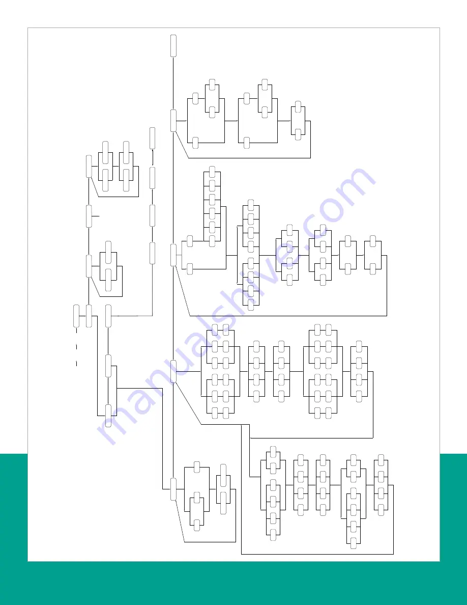
Figure 28: PROG > CHx > ACTIV, SYSTM, PIPE and I/O menus

40

Summary of Contents for DigitalFlow XGF868i

Page 1: ...DigitalFlow XGF868i Panametrics flare gas flow transmitter Programming manual...

Page 2: ...ii...

Page 3: ...DigitalFlow XGF868i Panametrics flare gas flow transmitter Programming manual 910 198P Rev C February 2015 iii...

Page 4: ...no content intended for this page iv...

Page 5: ...onsibility of the user to make sure all local county state and national codes regulations rules and laws related to safety and safe operating conditions are met for each installation Auxiliary equipme...

Page 6: ...avoid the dissemination of those substances in our environment and to diminish the pressure on the natural resources we encourage you to use the appropriate take back systems Those systems will reuse...

Page 7: ...ssure switch 7 1 8 Entering setup data 8 1 8 1 Setting transducer signal parameters 8 1 8 2 Initializing setup parameters default setup 10 1 8 3 Setting response time V averaging 10 1 8 4 Using advanc...

Page 8: ...endix B Data records 45 B 1 Available option cards 45 B 2 Option cards installed 45 B 3 Setup data 46 Appendix C Programming the XGF868i with PanaView 51 C 1 Introduction 51 C 2 Programming with PanaV...

Page 9: ...the meter 76 C 9 2 Saving new site data to the XGF868i 77 C 9 3 Saving a site to the PC 77 C 9 4 Clearing a site from the meter 77 C 9 5 Saving site data in text form 77 Appendix D PanaView menu maps...

Page 10: ...x...

Page 11: ...and running as quickly as possible you must as a minimum activate the channel s enter the channel and global system data and the pipe parameters The procedure options section at the end of each menu...

Page 12: ...a hazardous area Six keys on the keypad enable users to program the XGF868i Enter confirms choice of a specific option and data entry within the option Escape allows users to exit from a specific opt...

Page 13: ...g To continue entering quick startup data proceed to step 3 in the following section To continue regular programming refer to Appendix A Menu Maps on page 39 to navigate to the desired menu To leave t...

Page 14: ...sands of LB Metric tons 1 000 KG Millions of LB Tons 2 000 LB 2 Scroll to the desired mass flow time units for the mass flow rate display and press enter 3 Scroll to the desired number of Mdot decimal...

Page 15: ...s the time required for the transducer signal to travel through the transducer and its cable This time delay must be subtracted from the transit times of the upstream and downstream transducers to ens...

Page 16: ...hen do one of the following If other was selected proceed to step 10 If air was selected proceed to step 11 10 Use the arrow keys to enter the fluid soundspeed in feet per second in the gas to be meas...

Page 17: ...es would be used to set up input B 1 7 3 Base temperature 1 Use the arrow keys to enter the base temperature and press enter The ratio of this value to the actual temperature is used to calculate the...

Page 18: ...a value for a parameter with menu options and press enter Procedure options After completing the above steps the XGF868i returns to the channel SET UP window Do one of the following To continue progra...

Page 19: ...an T offset 500 to 500 sec 58 sec At this prompt specify a time measurement offset that compensates for any shift resulting from cross correlation Set to 0 for active skan T offset of peak 1 to 100 50...

Page 20: ...V averaging Use this option to specify the number of readings that occur before the meter will respond to a step change in flow rate In general the smaller the number of readings the less steady the d...

Page 21: ...es Procedure options After completing the previous steps the XGF868i returns to the advanced features window Do one of the following To continue programming refer to Appendix A Menu Maps on page 39 to...

Page 22: ...pt scroll to Eng to display measurements in English units or to metrc for metric units and press enter 5 Scroll to the desired pressure units absolute or gauge and press enter 6 Do one of the followin...

Page 23: ...three submenus are included in this section Error program the meter s response during an error condition see below Optn set up any option cards and the slot 0 analog outputs see Setting up slot 0 and...

Page 24: ...o the global I O window Do one of the following To continue programming refer to Appendix A Menu Maps on page 39 to navigate to the desired menu To leave the keypad program press escape four times 1 9...

Page 25: ...downstream ultrasonic signal transit time N A N A DELTA Displays the transit time difference between the upstream and downstream signals N A N A Tot K K factor based on the Reynolds number N A N A PE...

Page 26: ...ed menu To leave the keypad program press escape three times 1 9 2d Analog inputs Refer to Figure 31 on page 43 and complete the following steps to set up the analog inputs of an option card installed...

Page 27: ...39 to navigate to the desired menu To leave the keypad program press escape four times 1 9 2f Frequency outputs The frequency output issues a continuous signal with a frequency proportional to the se...

Page 28: ...serial interface go to procedure options 1 9 3b Setting up MODBUS communications When equipped with an optional MODBUS output card the XGF868i can transmit flow data serially to a flow computer or SCA...

Page 29: ...t int 5 8 Ch1 Act volumetric Q DIGITS 4 IEEE 32 bit 7 C Ch1 Std volumetric Q DIGITS 4 IEEE 32 bit 9 10 Ch1 Fwd totals T DIGITS 4 2 16 bit int 11 14 Ch1 rev totals T DIGITS 4 2 16 bit int 13 18 Ch1 tot...

Page 30: ...54 6A Ch2 timer 2 4 2 16 bit int 56 6E Ch2 error code 0 2 57 70 Ch2 sound speed 3 4 2 16 bit int 59 74 Ch2 molecular weight 4 4 2 16 bit int 61 78 Ch2 sig strength upstream 1 4 2 16 bit int 63 7C Ch2...

Page 31: ...508 3F6 2MODBUS baud rate 0 2 509 3F8 3MODBUS parity 0 2 510 3FA 4MODBUS stop bits 0 2 511 3FC MODBUS meter addr 0 2 512 3FE RESERVED 1 Clear totalizers Flag from the 8051 to clear either the channel...

Page 32: ...secur and press enter 4 At the lock out prompt scroll to UNlck to unlock the system and return to the initial program menu or scroll to lock to lock the system NOTE If the system was unlocked at the...

Page 33: ...ogram window scroll to prog and press enter 4 In the prog menu scroll to GLOBL and press enter 5 Scroll to I O and press enter 6 Scroll to LCD and press enter 7 The window now asks for the of LCD para...

Page 34: ...page 25 NOTE For information on the logging output see Chapter 3 logging data 2 3 2 The text display output To collect data from the instrument and display it on a text screen complete the following s...

Page 35: ...n the context menu NOTE After resizing or removing any of the multiple text screens the default tiled layout may be restored by opening the window menu see the PanaView user s manual and clicking on t...

Page 36: ...the selected process parameter s as a function of time at the interval specified in step 3 5 While PanaView is graphing the data the following actions may be taken from the control pane change the sam...

Page 37: ...To select a different signal type open the signal menu at the right shown here with raw upstream highlighted and click on the desired signal 2 3 3b Plotting transducer signals To plot the selected si...

Page 38: ...28...

Page 39: ...gging capability with PanaView 3 2 Logging with PanaView PanaView is capable of creating and viewing log files of the following types Meter logs log files stored in the XGF868i memory as discussed abo...

Page 40: ...iven starttime Double click on OK to agree to the given time on now to start the log immediately or on edit to change the starting time j If you select edit PanaView asks first for the desired hour th...

Page 41: ...year then for the month and finally for the day For each parameter type the desired number in the right window or scroll to and click on the desired month and click next item or simply click next item...

Page 42: ...n the log browser dialog box are unavailable 2 Double click on the computer name to advance to the dialog box shown in Figure 15 below Figure 15 Log type selection 3 Double click on PC logs to advance...

Page 43: ...e logs the tree will appear similar to Figure 19 below Figure 19 Expanded meter logs option 2 Double click on the desired log A window opens for the individual log as shown in Figure 20 below Figure 2...

Page 44: ...n buttons listed in step 2 above You can monitor the progress of an ongoing log in several ways Click on the log items tab see Figure 21 on page 33 for a list of the parameters specified for logging C...

Page 45: ...1 Installation of the Startup guide for instructions on wiring the RS232 serial port For additional information refer to the EIA RS Serial communications manual 916 054 After making the hardware conne...

Page 46: ...no content intended for this page 36...

Page 47: ...led information on creating a log file see Chapter 3 Logging data on page 29 For detailed information on programming site data see Chapter 1 Programming site data on page 1 IMPORTANT None of the clear...

Page 48: ...logs or on the communication port name and the meter name to access the stored meter logs In either case the log browser appears similar to Figure 25 below Figure 25 Log browser window 4 Highlight th...

Page 49: ...Maps are included in this appendix Figure 28 on page 40 PROG CHx ACTIV SYSTM PIPE I O Menus Figure 29 on page 41 PROG CHx SETUP Menu Figure 30 on page 42 PROG GLOBL SYSTM I O COMM Menus Figure 31 on...

Page 50: ...nglish PIPE OD inch feet mm m Metric English PATH LENGTH P PIPE WALL inch feet mm m Metric English AXIAL LENGTH L Other Air FLUID TYPE FLUID SOUNDSPEED On Off REYNOLDS CORRECTION CALIBRATION FACTOR KI...

Page 51: ...LOCITY HIGH LIMIT VELOCITY LOW LIMIT SOUNDSPEED LIMIT CORR PEAK LIMIT SIGNAL LOW LIMIT INIT AVRG ADVAN NO YES 1 2 5 30 60 STATS 10 Signal defaults RESPONSE TIME MULTK MASS Multi K factors Static densi...

Page 52: ...s 28 and 29 Eng METER MESSAGE Metric PRESSURE UNITS SYSTEM UNITS PSIa PSIg BARa BARg Kpaa Kpag Metric English ATMOSPHERIC PRESSURE 1 CHANNEL UNITS 2 CHANNEL UNITS VOLUMETRIC UNITS LCD HOLD LOW HIGH HH...

Page 53: ...utputs C D A B TEMP OFF Input measurement LABEL RTD inputs ZERO value FULL scale value C D A B FREQ OFF CH1 CH2 SUM DIF AVE Measurement name Slot 1 outputs TOTL TOTL TIME MDOT VEL VOLUM SS up SS do SN...

Page 54: ...44...

Page 55: ...frequency outputs 1473 15 FRI 2 frequency outputs 1 RTD input 1 current input 1345 04 Modbus communications protocol 1385 HART communication 1477 03 2 MODBUS TCP IP 1477 01 Ethernet 1475 01 Foundatio...

Page 56: ...Channel status Off Burst Channel status Off Burst Measure mode Skan S M Measure mode Skan S M Channel system Channel label Channel label Site channel msg Channel message Vol units Vol units Vol time...

Page 57: ...ngth P Path length P Axial length L Axial length L Fluid type Air Other Fluid type Air Other Other Sndspd Other Sndspd Calibration factor Calibration factor Channel input output Zero cutoff Zero cutof...

Page 58: ...p data Channel SETUP advanced features multi K factors K factor Velocity K factor K factor Velocity K factor 1 1 2 2 3 3 4 4 5 5 6 6 7 7 8 8 9 9 10 10 11 11 12 12 13 13 14 14 15 15 16 16 17 17 18 18 1...

Page 59: ...y Fluid density Mole weight Mole weight Global system Meter message Totalizer units System units English Metric Tot dec digits Pressure units Mass flow Atmos pressure Mass flow time Vol units MDOT dec...

Page 60: ...50...

Page 61: ...nel status activate one or both channels and select the desired measurement method Channel system enter the individual channel parameters Channel pipe enter the pipe parameters Channel I O set up the...

Page 62: ...ht the my computer name branch by clicking on it 3 Pull down the edit menu by clicking on it in the menu bar 4 Click on the new menu option to select it and a submenu opens with two choices on it see...

Page 63: ...ed to install the Ethernet device discovery software utility available with your XGF868i on a PC connected to the LAN Once installed and running the software displays all Ethernet devices currently co...

Page 64: ...ption to select it 4 The new IDM meter screen see Figure 36 below opens Enter the network ID number for the meter and click ok Figure 36 New IDM meter screen IMPORTANT The network ID number must match...

Page 65: ...on page 54 click on the XGF entry The screen now appears similar to Figure 39 below Figure 39 Meter tree with edit functions option 2 Expand the edit functions option The window now appears similar t...

Page 66: ...tings you have modified or left unchanged as shown in Figure 43 below If you modify or step through more than five items a scroll bar at the right of the panel lets you review the earlier settings Fig...

Page 67: ...View returns to the channel program menu see Figure 41 on page 55 Proceed to the system option C 5 2 Entering data in the channel system option 1 From the channel program menu highlight and double cli...

Page 68: ...The first prompt asks for the transducer number For a standard transducer double click on the standard option in the center pane Then enter the number engraved on the transducer head in the right pane...

Page 69: ...t pane and click next item NOTE If a spoolpiece was ordered with the meter the transducer signal path length P and the transducer signal axial length L are engraved on the flowcell and or are included...

Page 70: ...d to base temperature on the next page 4 Select input A or input B and click next item The inputs were labeled during setup NOTE The set up of input A is used as an example Identical procedures would...

Page 71: ...rs Range Default value Description Signal low limit 20 to 100 20 The E1 LOW SIGNAL error message appears when the signal strength falls below the programmed SIGNAL LOW LIMIT value See Chapter 2 in the...

Page 72: ...to 100 50 The percentage of peak used to calculate the transit times and Delta T is specified at this prompt M S switch 0 to 250 sec 50 sec If the burst mode is set to skan measure S M the meter switc...

Page 73: ...e multi K factors or on no to disable this option If NO was selected the meter returns to the advanced features window If YES was selected proceed to step 3 3 Double click on the desired custom type v...

Page 74: ...e 45 System option in the global menu 3 Double click on the desired system units selection either metric or English The XGF868i will display all parameters and measurements in the designated units 4 D...

Page 75: ...l programmed data in Appendix B Data records on page 45 The I O submenu consists of the following options Error handling program the meter s response during an error condition Options set up any optio...

Page 76: ...ge measurements below C 6 2b The error option NOTE The 2PATH ERROR HANDLING option is intended for applications where two sets of transducers are installed in the same location in the same pipe to imp...

Page 77: ...ns specific to the type of input or output selected above Analog outputs Complete the following steps to set up the analog outputs for any slot refer to Figure 58 on page 83 1 Double click on the desi...

Page 78: ...transit Displays the upstream ultrasonic signal transit time N A N A DN transit Displays the downstream ultrasonic signal transit time N A N A Delta T Displays the transit time difference between the...

Page 79: ...prompt the meter returns to step 1 Click exit page to proceed to another menu or option Option card analog inputs Complete the following steps to set up the analog inputs of an option card installed i...

Page 80: ...vailable at the above prompt 4 Double click on the desired measurement name Table 25 on page 68 provides a description of the available parameters NOTE The measurement units that appear in these promp...

Page 81: ...m port submenu and returns to the global program prompt NOTE The XGF868i MODBUS communication settings chosen in the next four steps must match those of the MODBUS control system 4 Double click on the...

Page 82: ...C Ch1 error code 0 2 23 24 2E Ch1 sound speed 3 4 2 16 bit int 24 26 32 Ch1 molecular weight 4 4 2 16 bit int 26 28 36 Ch1 sig strength upstream 1 4 2 16 bit int 28 30 3A Ch1 sig strength downstream 1...

Page 83: ...gth upstream 1 4 2 16 bit int 61 63 7C Ch2 sig strength downstream 1 4 2 16 bit int 63 65 80 Ch2 temperature 2 4 2 16 bit int 65 67 84 Ch2 pressure 3 4 2 16 bit int 67 69 88 Avg velocity 2 4 2 16 bit...

Page 84: ...an 2 in error 2 chan 1 in error 3 both ok 5 MODBUS baud rate 5 2400 6 4800 7 9600 6 MODBUS parity 0 none 1 odd 2 even 7 MODBUS stop bits 1 1 stop bit 2 2 stop bits 8 General Registers are written if c...

Page 85: ...ow appears similar to Figure 46 below Highlight and double click on the security option in the center pane Figure 46 Global menu with security option highlighted 2 If the system is locked the window i...

Page 86: ...s option The window now appears similar to Figure 50 below Figure 50 Properties window 3 Click on the site files button The site file operations window as shown in Figure 51 below opens Figure 51 Site...

Page 87: ...the site file operations window you must close and reopen the window to click on the new site C 9 4 Clearing a site from the meter As the XGF868i has only one site loaded working at any time it is not...

Page 88: ...78...

Page 89: ...maps are included in this appendix Figure 55 on page 80 PanaView prog CHx ACTIV SYSTM PIPE I O menus Figure 56 on page 81 PanaView prog CHx SETUP menu Figure 57 on page 82 PanaView prog GLOBL SYSTM I...

Page 90: ...IPE OD inch feet mm m Metric English PATH LENGTH P PIPE WALL inch feet mm m Metric English AXIAL LENGTH L Other Air FLUID TYPE FLUID SOUNDSPEED Yes No REYNOLDS CORRECTION KINEMATIC VISCOSITY VOLUMETRI...

Page 91: ...ATS 10 Signal defaults RESPONSE TIME MULTK MASS Multi K factors Static density No Yes CstV CstR NO YES Kin viscosity Edit table Enter of K factors velocity Reynolds K factor Repeat for the of K factor...

Page 92: ...RIC UNITS Display HOLD LOW HIGH HHIGH OTHER YES NO 2 PATH ERROR HANDLING OF LCD PARAMS SUM DIF AVE CH1 CH2 TOTL TOTL TIME MDOT VEL VOLUM SS up SS do SNDSP T up MASS MASS REYN Tot K PEAK Qup Tdown DELT...

Page 93: ...H1 CH2 SUM DIF AVE Measurement name Slot 1 outputs TOTL TOTL TIME MDOT VEL VOLUM SS up SS do SNDSP T up MASS MASS REYN Tot K PEAK Qup Tdown DELTA AMPdn CNTup CNTdn P up Qdown AMPup PRESR Z AcVOL StVOL...

Page 94: ...84...

Page 95: ...Avg fwd mass totals MTOT_U Ch1 rev mass tTotals MTOT_U Ch2 rev mass totals MTOT_U Avg rev mass totals MTOT_U Ch1 mass tot digits none Ch2 mass tot digits none Avg mass tot digits none Ch1 molecular we...

Page 96: ...the tree under GEFlow XGF 2 Select the others tab and open the drop down list for the PRIMARY_SELECTOR and SECONDARY_SELECTOR refer to Figure 60 on page 86 3 Choose the unit from the list see Figure...

Page 97: ...d the PRIMARY_SELECTOR was set to use velocity you would choose m s for the unit as shown in Figure 61 below Figure 61 Units index drop down list E 5 Resetting instrument totalizers To reset the instr...

Page 98: ...ditor The flowmeter AI blocks along with the AO and PID of another device on the network are displayed We have connected the AI_1 OUT of the flowmeter to the CAS IN of the AO block We have also connec...

Page 99: ...s arising from course of dealing or usage or trade Return policy If a Panametrics instrument malfunctions within the warranty period the following procedure must be completed 1 Notify Panametrics givi...

Page 100: ...eduction targets across critical industries including Oil Gas Energy Healthcare Water and Wastewater Chemical Processing Food Beverage and many others Join the conversation and follow us on LinkedIn l...

Reviews: