background image


21 

21 

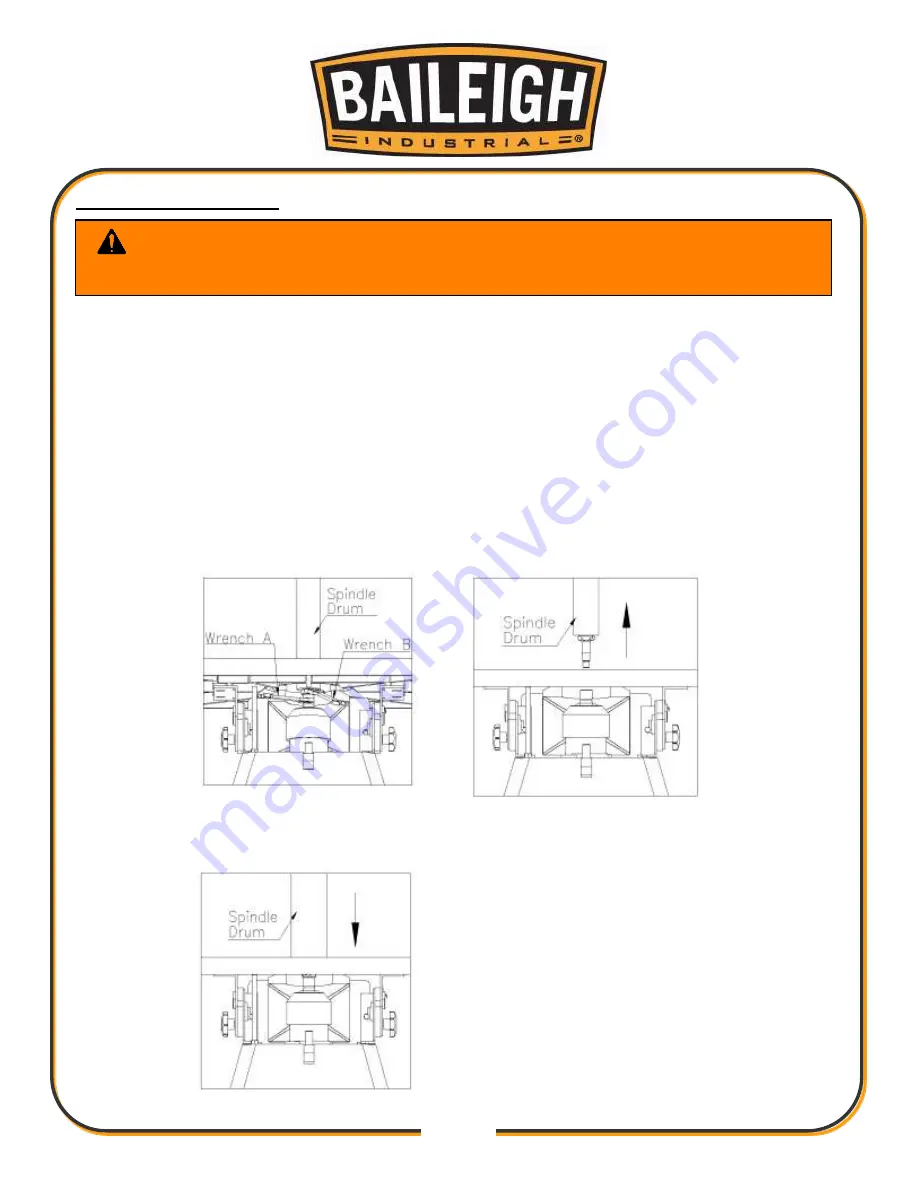
Mounting Spindle Drum 


1.  Disconnect the sander from the power source. 

1.  Select the proper diameter of spindle drum. 

2.  Clean the taper part of the spindle drum before mounting it into the spindle. 

3.  Use an open-end wrench to lock the spindle by holding its flat surface. At the same time, 

use another open-end wrench to tighten the spindle drum. 

4.  Lift straight upward on the spindle drum to remove it. 

5.  Install the spindle squarely into the chuck. 

6.  Tighten using two wrenches. Do not over tighten the spindle drum or it will be causing 

removable problem. 


WARNING:

  ALWAYS disconnect power to the machine before changing 

spindles or working on it for any reason. 

Use a wrench to lock the 
spindle. Use another wrench 
to loosen the spindle drum. 

Fitting a new spindle drum. 

Removing an old spindle drum 

Summary of Contents for OS-2424

Page 1: ...IGH INDUSTRIAL INC IS PROHIBITED Baileigh Industrial Inc does not assume and hereby disclaims any liability for any damage or loss caused by an omission or error in this Operator s Manual resulting fr...

Page 2: ...NTENTS 11 Cleaning 11 TRANSPORTING AND LIFTING 12 INSTALLATION 12 OVERALL DIMENSIONS 14 GETTING TO KNOW YOUR MACHINE 15 ELECTRICAL 16 Power cord connection 18 OPERATION 19 Tilting the Table 20 Adjust...

Page 3: ...e to Seller of any suspected defect in the Goods prior to the expiration of the warranty period The original end user must also obtain a RGA from Seller prior to returning any Goods to Seller for warr...

Page 4: ...urther remedies provided under this Agreement or at law or equity Attorney s Fees In the event legal action is necessary to recover monies due from Buyer or to enforce any provision of this Agreement...

Page 5: ...tion of the functional parts of the machine Capacity charts Set up and start up instructions Machine operation Scheduled maintenance Parts lists GENERAL NOTES After receiving your equipment remove the...

Page 6: ...es a hazard or unsafe practice that will result in severe Injury or Death Safety signs with signal word DANGER or WARNING are typically near specific hazards General precautions are listed on CAUTION...

Page 7: ...ct against objectionable or uncomfortable loud noises DUST HAZARD Wear appropriate dust mask Dust created while using machinery can cause cancer birth defects and long term respiratory damage Be aware...

Page 8: ...EAS DO NOT assume the power to be off FOLLOW PROPER LOCKOUT PROCEDURES Power Switch with Lock Out In the event of incorrect operation or dangerous conditions the machine can be stopped immediately by...

Page 9: ...y trained and qualified personnel should operate this machine 3 Make sure guards are in place and in proper working order before operating machinery 4 Respirator Use Always use a mask or respirator ap...

Page 10: ...be thrown from the machine 19 Observe work area conditions DO NOT use machines or power tools in damp or wet locations Do not expose to rain Keep work area well lighted DO NOT use electrically powered...

Page 11: ...e Material Only use this sander for natural wood stock It is NOT recommended to sand particle board plastics laminates medium density fiber board MDF metal glass ceramics or products containing asbest...

Page 12: ...90 and asking for the support desk for purchased machines Tech Support handles questions on machine setup schematics warranty issues and individual parts needs other than die sets and blades For speci...

Page 13: ...y damage painted surfaces Follow manufacturer s label instructions when using any type of cleaning product After cleaning wipe unpainted metal surfaces with a light coating of quality oil or grease fo...

Page 14: ...securing bolts that attach the machine to the pallet Approaching the machine from the side lift the machine on the frame taking care that there are no cables or pipes in the area of the forks Move the...

Page 15: ...recise placement of it to the mounting surface FLOOR This tool distributes a large amount of weight over a small area Make certain that the floor is capable of supporting the weight of the machine wor...

Page 16: ...14 14 OVERALL DIMENSIONS 24 610 24 610 39 990...

Page 17: ...15 15 GETTING TO KNOW YOUR MACHINE...

Page 18: ...will damage the motor In the event of a malfunction or breakdown grounding provides a path of least resistance for electric current to reduce the risk of electric shock This tool is equipped with an...

Page 19: ...service personnel if the grounding instructions are not completely understood or if in doubt as to whether the tool is properly grounded Repair or replace damaged or worn cord immediately Extension Co...

Page 20: ...the cord to the power supply is a way that does NOT create a trip hazard 3 Connect the power cord to the power supply and check that the power cord has not been damaged during installation 4 When the...

Page 21: ...s loosen both table lock and tilting gear lock before changing the angle position of the table Never force the table if it does not tilt easily the reason may be that the locks are still engaged Never...

Page 22: ...the table and drum has been set by the factory before shipment However after a long period of operation the vertical angle may become inaccurate 2 To adjust the vertical angle set the table to a flat...

Page 23: ...ther open end wrench to tighten the spindle drum 4 Lift straight upward on the spindle drum to remove it 5 Install the spindle squarely into the chuck 6 Tighten using two wrenches Do not over tighten...

Page 24: ...The table below shows which table insert to use for various drum diameters Drum Number Drum Dimension Table Insert 1 1 4 Dia x 5 long 1 2 3 8 Dia x 6 long 1 3 1 2 Dia x 6 long 1 4 5 8 Dia x 6 long 1...

Page 25: ...1 4 up on sight glass We recommend that a small amount of grease be applied to table tilting screw once a month No lubrication is required for the bearings they are permanently lubricated Apply rust i...

Page 26: ...nding load Motor overheating Motor is dirty Motor is damaged Clean motor Check and repair motor Excessive machine vibration Machine is incorrectly leveled Adjust machine leveling Mark on workpiece San...

Page 27: ...25 25 PARTS DIAGRAM 1...

Page 28: ...Oil Indicator 1 14 30101014 Oil Seal 1 15 S0526300 C Snap Ring 1 16 C1206206 Bearing 1 17 30101003a Motor Seat 1 18 M000000 Motor 1 19 L000000 Motor Cord 1 20 30101002G 1 Oil Indicator Cover 1 21 301...

Page 29: ...crew 2 49 30101004 Oil Plug 1 50 S0230506 Spring Washer 5 16 10 51 S0410525 Key 1 52 S0710205 Pivot Nail 1 53 S0030310 Round Cross Screw 3 16 24unc 5 8 4 54 S0110300 Nut 3 16 24unc 2 55 S0010410M Hex...

Page 30: ...1 30105058 Washer 4 2 72 30105059 Nut 3 4 6 73 30105060 Sanding Sleeve 4 1 74 30105057 PVC 4 1 75 S0313525 Pin 3 5 25 10 76 30105056 Hex Nut 3 4 6 77 30105055 Spindle 3 4 6 78 30105063 Washer 3 2 79 3...

Page 31: ...29 29 NOTES...

Page 32: ...INDUSTRIAL LTD UNIT 1 FULLWOOD CLOSE SWIFT VALLEY INDUSTRIAL ESTATE RUGBY WEST MIDLANDS CV21 1QH UNITED KINGDOM PHONE 44 0 24 7661 9267 FAX 44 0 24 7661 9276 WWW BAILEIGHINDUSTRIAL CO UK BAILEIGH IND...

Reviews: