background image

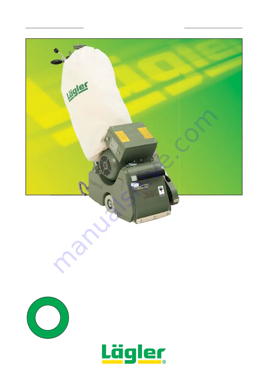
BELT SANDING MACHINE HUMMEL

®

HUMMEL

®

English / Englisch

S

ta

u

b


-


d

us

t


-


p

ou

ss

re

 - p

o

lv

o

S

ta

u

b


-


d

us

t


-


p

ou

ss

re

 - p

o

lv

o

 -  -


<


1

mg/m³

Operation, 

Maintenance, Safety

Translation of original operating instructions 

for the belt sanding machine

00.100.20.002     01.12.2012

*00.100.20.002*

Summary of Contents for HUMMEL

Page 1: ...sh Englisch S t a u b dust po u s s i r e p o lv o S t a u b dust po u s s i r e p o lv o 1 mg m Operation Maintenance Safety Translation of original operating instructions for the belt sanding machin...

Page 2: ...ssemblies of the HUMMEL belt sanding machine Cable support with strain relief ring ON OFF switch Switch box Lowering lever Handle Guide tube Safety guard Side cover Lateral wheel Drive motor Belt guar...

Page 3: ...k and replacement of wearing parts 29 7 1 Cleaning and care instructions 30 7 2 Lubrication 33 7 3 Checking and setting the sanding belt tracking 33 7 4 Checking the machine setting 36 7 5 Checking th...

Page 4: ...odenandcorkfloors plasticskatingrinksandtartanrunningtracks A specially equipped version of the machine can be used to sand sheet metal surfaces Any application other than that described here is inadm...

Page 5: ...ll maintenance work and work on the electrical equipment Avoid body contact with grounded parts e g pipes radiators ovens refrigerators The quality of the motor cable and the power cables must match t...

Page 6: ...paint oil and wax manufacturers Cloths pads et cetera which have been immersed in oil or wax can spontaneously combust Be certain to note the warning notices of the paint oil and wax manufacturers Th...

Page 7: ...ng on the machine make sure that all tools and adjustment tools have been removed from the machine The machine may not be started when tilted backward or forward The machine may not be started if the...

Page 8: ...uces noise RISK OF PROPERTY DAMAGE Do not store the unused machine on the sanding drum Otherwise the sanding media can cause scratches on the ground or the sanding drum can be damaged Improper transpo...

Page 9: ...or damage Before using the machines you must inspect the safety devices or damaged parts carefully to ensure that they are working perfectly and as intended Check whether the moving parts are working...

Page 10: ...weight of the machine 79 kg 174 lbs Dust emissions at workplace 1 mg m 0 012 gr cu yd measured as per the testing requirements GS HO 15 of German statutory accident insurance DGUV Workplace related no...

Page 11: ...ty switch for fault current PRCD S for German mains supply safety belt Wearing parts Please check the condition of the wearing parts mentioned below at regular intervals in order to be able to work sa...

Page 12: ...tainer for storage or transportation of the machine Section 6 Transport and storage Please ensure that the packaging materials are responsibly disposed of 2 Press the lowering lever at the handle down...

Page 13: ...the tensioning roller 10 Position the sanding belt on the tensioning roller of the drive unit Fig 9 and push it over the tensioning roller and the sanding drum Fig 10 Fig 6 Hook the cable support into...

Page 14: ...RISK OF PROPERTY DAMAGE from rotating parts of the machine Always tension the sanding belt before switch on the machine Fig 12 Always lift the sanding drum off the floor before switch on the machine F...

Page 15: ...country 1 Lift the sanding drum off the floor by turning the lowering lever at the handle upwards Fig 14 2 Insert the plug of the motor cable in the coupler of the extension cable Fig 15 1 3 Fasten t...

Page 16: ...ORKING Fig 18 ATTENTION Remaining for too long in the switch position START shortens the service life of the starting capacitor 4 3 2 MACHINES WITH THREE PHASE AC MOTOR MAINS VOLTAGE 400 V 1 Lift the...

Page 17: ...phase changing switch turn the screwdriver at 180 against a small resistance Fig 22 2 ATTENTION The phase changing switch can only be turned in one direction 4 3 3 GENERAL If the motor should ever be...

Page 18: ...from the socket after you have switched off the machine Secure the machine against sliding For example place a flat piece of wood between the floor surface and machine housing Fig 25 ATTENTION Do not...

Page 19: ...ng marks made by previously used grit grade by adhering to the order of the sandpaper grit grade and never skip more than one grit grade Always vacuum the floor thoroughly before the first sanding ope...

Page 20: ...f the drive unit upwards Fig 27 3 This will lower the tensioning roller 5 Remove the worn sanding belt from the tensioning roller and the sanding drum Fig 28 6 Position the new sanding belt on the ten...

Page 21: ...g belt before switch on the machine Fig 32 Always lift the sanding drum off the floor before switch on the machine Fig 26 10 Before sanding the precise tracking of the sanding belt must be checked Adj...

Page 22: ...nated on the notch plate as GROB MITT FEIN Fig 34 The pressure stage indications relate to the grit grade sequence The sanding pressure should be adjusted inline with the grit grade sequence and reduc...

Page 23: ...event a deterioration of the suction performance due to the lack of filtering surface area Do not work with an overfilled dust bag The dust bag must be emptied outdoors When emptying the dust bag wear...

Page 24: ...ing Oil or wax can lead to spontaneous combustion Therefore the machine must always be cleaned carefully before transport or storage Always transport and store the machine without the dust bag Store t...

Page 25: ...ng the dust bag 4 Loosen the two motor nuts at the motor bearing bracket Fig 40 The motor nut must only be backed out from the fitting between the motor nut and motor bearing bracket and not completel...

Page 26: ...nd allow the drive belt to run off the lower pulley Fig 45 If necessary use the box wrench see tool kit to turn the lower pulley exclusively clockwise ATTENTION Only turn the nut with the box wrench a...

Page 27: ...t the machine housing Fig 51 4 Lift the sanding drum off the floor by turning the lowering lever at the handle upwards Fig 52 Fig 49 When inserting the guide tube make sure that the upper rod of the l...

Page 28: ...lways transport and store the machine without the dust bag Store the emptied dust bag in a closed non combustible container If you wish to keep the machine in storage for a protracted period ensure th...

Page 29: ...ts on the newly sanded wooden floor You could cause scratches or other damage to the floor Never use any cleaning products which contain solvents Periodically but at the latest when you notice that da...

Page 30: ...um for damage Clean the parts carefully and ensure that the rubber coating on the rollers is not damaged Check the sanding belt tracking and adjust it if necessary using a grit grade 120 sanding belt...

Page 31: ...the right of the machine housing Fig 58 2 4 Pull the operating lever of the drive unit upwards Fig 58 3 This will lower the tensioning roller 5 Remove the sanding belt from the tensioning roller and...

Page 32: ...4 Guide rollers which are not rotatable easily provoke sparking during sanding and must be replaced without fail Part number in Section 11 Spare parts 10 Reassemble in reverse order 11 After mounting...

Page 33: ...lubrication points Fig 65 A Top part of the rod linkage at the lever plate B Lever plate on the handle shaft To do this tilt the machine slightly to one side and allow a small amount of oil to run int...

Page 34: ...230 V and 220 V Turn the switch button in position TEST and hold the switch button for around 2 seconds in this position Fig 68 At the same time control the sanding belt tracking After this release th...

Page 35: ...le sanding belt This is because the more flexible the sanding belt the precisely it is possible to set the tensioning roller Mount the sanding belt Section 5 2 Changing the sanding belt and carry out...

Page 36: ...lt 8 If the sanding belt tracking is seen to be not correct after adjusting once repeat the process 9 After successful setting of the sanding belt tracking mount the side cover Fig 71 7 4 CHECKING THE...

Page 37: ...he nut of the setting fixture Fig 74 5 If the machine is sanding more heavily on the belt guard side A in Fig 75 the wheel must be adjusted away from the belt guard direction of B in Fig 75 If the mac...

Page 38: ...for blockages or deposits 7 6 REPLACEMENT OF SANDING DRUM Use exclusively original L GLER sanding drums Part number in Section 11 Spare parts 1 Switch off the machine and pull the power plug out of t...

Page 39: ...Part number in Section 11 Spare parts 1 Remove the drive unit Section 7 1 1 Dismantling and cleaning of drive unit 2 Clamp the drive unit in a vise If you are unable to reach the lock nuts with the c...

Page 40: ...screws are not tightened they will loosen during operation of the machine and fall on rotating parts ATTENTION If the lock nuts of the fixing screws are not tightened the tensioning roller can move ou...

Page 41: ...sing and hold onto the nut Mount the washers and the screw 7 8 2 REPLACEMENT OF COMPLETE REAR WHEEL ASSEMBLY 1 Switch off the machine and pull the power plug out of the socket 2 Tilt the machine forwa...

Page 42: ...screw again ATTENTION The lateral wheels must always be exchanged in pairs TIP As it is so easy and quick to exchange the lateral wheels and the back wheel it is advisable to use a second set of whee...

Page 43: ...V belt Fig 96 1 7 Turn the belt tensioner clockwise to release the tension of the suction V belt Fig 96 2 CAUTION RISK OF INJURY During dismantling and mounting the V belts take care of your fingers...

Page 44: ...3 Loosen the two nuts at the eye bolt at the motor Fig 99 and turn them upwards 4 Tension the drive V belt for the sanding drum by turning the eye bolt at the motor clockwise Fig 100 1 Correct tension...

Page 45: ...rom belt tensioner to fan pulley increase the wearing of fan axle pulleys and V belt extensive Fig 103 Then these parts must be replaced significant more often 6 Turn the belt tensioner counterclockwi...

Page 46: ...t also be confirmed Ensure that only original L GLER spare parts are used for maintenance work You should only allow the customer service work to be conducted by L GLER or an authorized L GLER service...

Page 47: ...r as is used extension and device connection cables with plugs connection cables with plugs movable cables with plugs and fixed connections Inspection interval Every 6 months as a reference value 3 mo...

Page 48: ...100 for 230 volts The temperature switch in the motor has switched off the machine because one or more power cables have a total length of more than 20 m the power cables has wire cross sections whic...

Page 49: ...uns but has no or very little sanding power capacity The sanding medium is incorrect or dull and must be replaced Section 5 2 Changing the sanding belt At low temperatures The machine is too cold and...

Page 50: ...damaged or worn out and must be replaced Section 7 10 Replacement and tensioning of V belts A pulley is dirty or worn out and must be cleaned or replaced There are clogged materials and deposits in th...

Page 51: ...grit grade of the sand ing belt and must be corrected Section 5 3 Regulating the sanding drum pressure The machine setting is not correct and must be adjusted The sanding drum must sands centrally Sec...

Page 52: ...he sanding drum while sanding The following causes must be eliminated additional weight is on the machine the rear part of the machine is lifted on with the handle while sanding the lowering lever at...

Page 53: ...or A C running capacitor Ha main winding Hi auxiliary winding B Phone 0049 7135 98 90 0 Fax 0049 7135 98 90 98 e mail info laegler com Internet http www laegler com N K1M 4 3 PE L1 N 1 2 L1 K1M 6 5 R...

Page 54: ...kW selector switch S1 operation temperature switch M1 motor 2 2 kW 220 230 V 60 CPS start operation stop test fuse 6 2 A fuse 6 2 A HUMMEL ELF single phase AC motor 2 2 kW 220 V 60 CPS 2 2 kW 230 V 60...

Page 55: ...en Frauenzimmern back up fuse 20 A power supply 220 V 60 CPS R1 8 6 kW selector switch S1 operation temperature switch M1 motor 2 9 kW 220 V 60 CPS USA version start operation stop test fuse 6 2 A fus...

Page 56: ...HUMMEL 01 12 2012 English Englisch SPARE PARTS 56 11...

Page 57: ...rew 36 100 33 01 100 Bracket 37 0933 1008 022 Screw 38 100 33 02 100 Grip 39 7337 1005 033 Rivet 40 100 01 01 100 Bumper felt 41 100 01 02 100 Sealing felt 42 9021 1005 000 Washer 43 0933 1006 014 Scr...

Page 58: ...HUMMEL 01 12 2012 English Englisch SPARE PARTS 58 11...

Page 59: ...t 12 00 000 41 002 Strain relief ring 13 100 20 26 100 Cable support complete 15 100 20 01 200 Guide tube 102 20 01 200 Guide tube USA 100 20 00 200 Guide tube complete 102 20 00 200 Guide tube USA co...

Page 60: ...HUMMEL 01 12 2012 English Englisch SPARE PARTS 60 11...

Page 61: ...ring with screw complete 20 100 04 06 200 Notch plate 21 7500 1005 012 Screw 22 100 04 02 100 Spring tensioner complete 23 100 05 00 200 Lateral wheel complete 24 0931 1008 050 Screw 25 100 04 00 100...

Page 62: ...HUMMEL 01 12 2012 English Englisch up to May 2000 from May 2000 Please state the machine number with each order SPARE PARTS 62 11...

Page 63: ...000 Nut 21 100 45 61 205 Screw 22 100 45 37 100 Double arm complete 23 100 02 05 100 Nut right hand thread 24 100 36 00 100 V belt pulley 25 0472 0047 000 Circlip 26 6005 0025 205 Ball bearing 28 6885...

Page 64: ...HUMMEL 01 12 2012 English Englisch SPARE PARTS 64 11...

Page 65: ...5 75 100 Motor cable 3 x 2 5 mm USA from year of manufacture 2008 000 65 43 257 Motor cable 3 x 2 5 mm USA up to year of manufacture 2007 105 65 75 100 Motor cable 5 x 1 5 mm for three phase AC motor...

Page 66: ...HUMMEL 01 12 2012 English Englisch SPARE PARTS 66 11...

Page 67: ...00 45 105 Box wrench 13 000 01 30 011 Tool bag empty 100 98 00 100 Tool bag complete 20 720 00 00 200 Trolley TRANSCART complete 21 000 01 10 011 Foldable earmuff type MUSIMUFF with FM radio 22 000 0...

Page 68: ...HUMMEL 01 12 2012 English Englisch NOTES 68...

Page 69: ...HUMMEL 01 12 2012 English Englisch NOTES 69...

Page 70: ...HUMMEL 01 12 2012 English Englisch NOTES 70...

Page 71: ...nature and company stamp Date of test and maintenance work Signature and company stamp Date of test and maintenance work Signature and company stamp Date of test and maintenance work Signature and com...

Page 72: ...d herewith that the machine Generic denomination Floor sanding machine Function Dry sanding of wooden floors Model HUMMEL Serial number See type plate Commercial name Belt sanding machine fulfils all...

Reviews: