5
5
11.
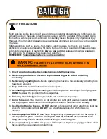
Do not overreach
. Maintain proper footing and balance at all times.
DO NOT
reach over or
across a running machine.
12.
Stay alert
. Watch what you are doing and use common sense.
DO NOT
operate any tool or
machine when you are tired.
13.
Check for damaged parts
. Before using any tool or machine, carefully check any part that
appears damaged. Check for alignment and binding of moving parts that may affect proper
machine operation.
14.
Observe work area conditions
.
DO NOT
use machines or power tools in damp or wet
locations. Do not expose to rain. Keep work area well lighted.
DO NOT
use electrically
powered tools in the presence of flammable gases or liquids.
15.
Keep children away
. Children must never be allowed in the work area.
DO NOT
let them
handle machines, tools, or extension cords.
16.
Store idle equipment
. When not in use, tools must be stored in a dry location to inhibit rust.
Always lock up tools and keep them out of reach of children.
17.
DO NOT operate machine if under the influence of alcohol or drugs
. Read warning
labels on prescriptions. If there is any doubt,
DO NOT
operate the machine.
18.
DO NOT
touch live electrical components or parts.
19.
Turn off
power before checking, cleaning, or replacing any parts.
20. Be sure
all
equipment is properly installed and grounded according to national, state, and
local codes.
21. Inspect power and control cables periodically. Replace if damaged or bare wires are
exposed.
Bare wiring can kill!
22.
DO NOT
bypass or defeat any safety interlock systems.
23. Keep visitors a safe distance from the work area.
Summary of Contents for MH-19
Page 1: ...OPERATOR S MANUAL POWER HAMMER MODEL MH 19 B8935 2015 Baileigh Industrial Inc Rev 04 2015...
Page 19: ...17 17 PARTS DIAGRAM Stand Frame Assembly Parts Diagram...
Page 20: ...18 18 Slide Block Assembly Parts Diagram...
Page 21: ...19 19 Pulley Assembly Parts Diagram...
Page 22: ...20 20 Crankshaft Assembly Parts Diagram...
Page 23: ...21 21 Clevis Shaft Assembly Parts Diagram...
Page 24: ...22 22 Bell Crank Assembly Parts Diagram...
Page 25: ...23 23 Main Lever Assembly Parts Diagram...
Page 26: ...24 24 Height Adjustment Assembly Parts Diagram...
Page 27: ...25 25 Left Hand Frame Assembly Parts Diagram...
Page 28: ...26 26 Guard Assembly Parts Diagram...
Page 35: ...33 33 NOTES...
Page 36: ...34 34...


