


25
25
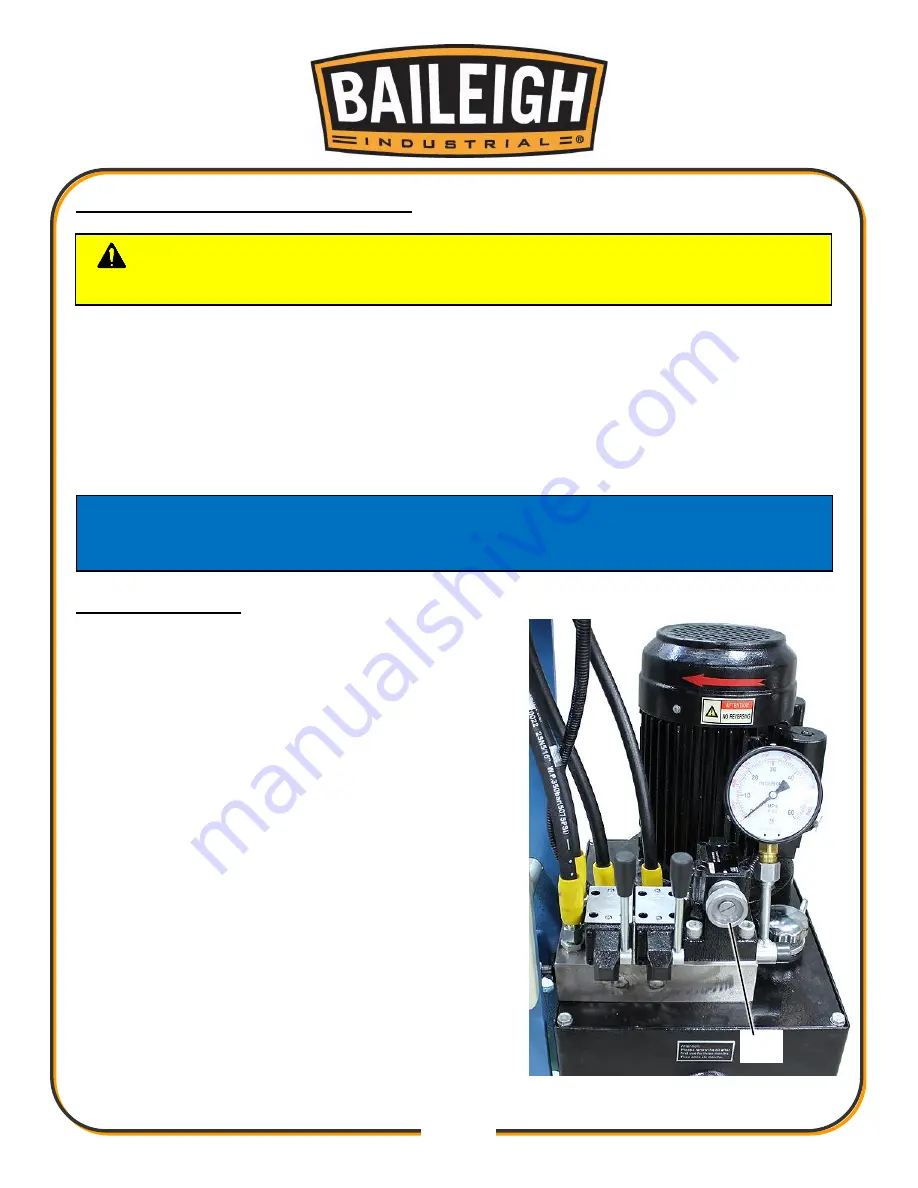
PRESSURE REGULATION VALVE
The pressure regulation valve (A) is located in the top cover of the hydraulic unit. With this valve
the maximum pressure, referring to the maximum press capacity, can be changed. Turning the
knob clockwise will increase the pressure, turning the knob counterclockwise will decrease the
pressure. Adjusting the pressure to meet the material can be very beneficial in completing the
pressing operation while reducing the change to damage the piece part.
Working at reduced pressure when available will also reduce the stress on the press and the
hydraulic system.
Pressure Adjusting
Pressure for the Main Ram must be set using the Main
Ram. Pressure for the Side Ram may be set using
either ram.
1. Start the hydraulic unit.
2. Make sure the piston is in rest position (no force
applied).
3. Set the table height in the top position.
4. Place the heal blocks on the table.
5. Loosen the lock nut behind the hand knob and turn
the knob counterclockwise 1/2 to 1 full turn to
reduce the pressure. Do not overturn and remove
the knob!
6. Extend the ram down until it reaches the heal
blocks. Hold the lever in the down position and read
the pressure on the pressure gauge.
7. Slowly turn the knob (A) of the regulator in or out as
desired to set the desired pressure.
NEVER
EXCEED THE MAXIMUM RAM PRESSURE
SETTING!
CAUTION:
NEVER EXCEED THE MAXIMUM PRESSURE SETTING FOR
THE RAM BEING USED!
NOTICE: The Main Ram Maximum pressure is 4350psi (30mPa).
The Side Ram Maximum pressure is 2465psi (17mPa).
The operator MUST reduce the operating pressure when using the Side Ram.
A
Summary of Contents for HSP-60M-C
Page 37: ...34 34 OVERALL MACHINE PARTS DIAGRAM...
Page 40: ...37 37 MAIN RAM PARTS DIAGRAM...
Page 42: ...39 39 SIDE RAM PARTS DIAGRAM...
Page 45: ...42 42 ELECTRICAL SCHEMATIC...
Page 46: ...43 43 HYDRAULIC DIAGRAM...