


11
11
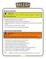
•
Improper connection of the equipment-grounding conductor can result in risk of electric
shock. The conductor with insulation having an outer surface that is green with or without
yellow stripes is the equipment-grounding conductor. If repair or replacement of the electric
cord or plug is necessary, do not connect the equipment-grounding conductor to a live
terminal.
•
Check with a qualified electrician or service personnel if the grounding instructions are not
completely understood, or if in doubt as to whether the tool is properly grounded.
•
Repair or replace damaged or worn cord immediately.
Extension Cord Safety
Extension cord should be in good condition and meet the minimum wire gauge requirements listed
below:
LENGTH
AMP RATING
25ft
50ft
100ft
1-12
16
16
14
13-16
14
12
12
17-20
12
12
10
21-30
10
10
No
WIRE GAUGE
An undersized cord decreases line voltage, causing loss of power and overheating. All cords
should use a ground wire and plug pin. Replace any damaged cords immediately.
Power cord connection:
3. Turn the main disconnect switch on the control panel to the OFF position.
4. Unwrap the power cord and route the cord away from the machine toward the power supply.
a. Route the power cord so that it will NOT become entangled in the machine in any
way.
b. Route the cord to the power supply is a way that does NOT create a trip hazard.
5. Connect the power cord to the power supply and check that the power cord has not been
damaged during installation.
6. When the hammer and dies area is clear of any obstruction. The main disconnect may be
turn ON to test the operation. Turn the main disconnect to OFF when the machine is not in
operation.
Summary of Contents for PH-28HD-VS
Page 1: ...OPERATOR S MANUAL POWER HAMMER MODEL PH 28HD VS B9045 2018 Baileigh Industrial Inc Rev 02 2018...
Page 18: ...16 16 PLATE ASSEMBLY...
Page 19: ...17 17 UPPER LOWER RAM ASSEMBLY...
Page 20: ...18 18 SPROCKET ASSEMBLY...
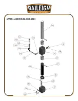
Page 21: ...19 19 SPRING ASSEMBLY...
Page 22: ...20 20 LEVER ASSEMBLY...
Page 23: ...21 21 SLIDE STROKE ASSEMBLY...
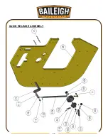
Page 24: ...22 22 QUICK RELEASE ASSEMBLY...
Page 25: ...23 23 V BELT ASSEMBLY POST...
Page 26: ...24 24 GUARD AND CONTROL BOX ASSEMBLY...
Page 33: ...31 31 NOTES...
Page 34: ...32 32 NOTES...
Page 35: ...33 33...
Page 36: ...34 34...