background image

2

BF-UM-C-DP C01-EN Novmber 2019


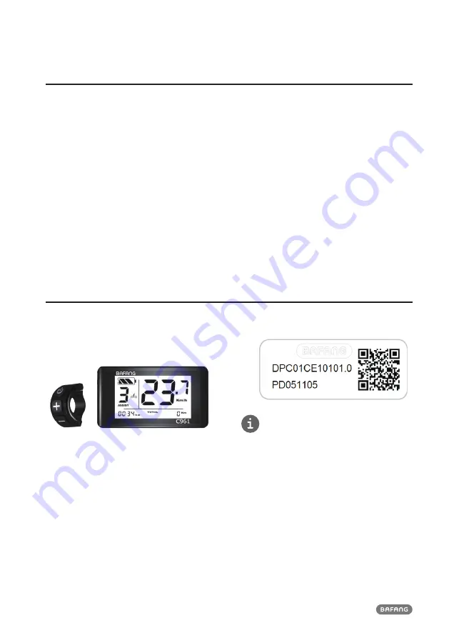
7.2 INTRODUCTION OF DISPLAY


• Model: DP C01.CAN BUS


• The housing material is PC and PVC:


• The label marking is as follows:


Note: 

Please keep the QR code label attached 

to the display cable. The information from the 

Label is used for a later possible software 
update.

7.1 IMPORTANT NOTICE


• If the error information from the display 

cannot be corrected according to the inst-
ructions, please contact your retailer.


• The product is designed to be waterproof. It 

is highly recommended to avoid submerging 
the display under water.


• Do not clean the display with a steam jet, 

high-pressure cleaner or water hose.


• Please use this product with care.


• Do not use thinners or other solvents to 

clean the display. Such substances can 
damage the surfaces.


• Warranty is not included due to wear and 

normal use and aging.

Summary of Contents for DP C01.CAN BUS

Page 1: ...rview 3 7 4 Display 4 7 5 Key Definition 4 7 6 Normal Operation 5 7 6 1 Switching the System ON OFF 5 7 6 2 Selection of Support Levels 5 7 6 3 Headlights backlighting 5 7 6 4 Walk Assistance 5 7 6 5 Reset mileage 5 7 6 6 Selection mode 5 7 6 7 Battery capacity indication 5 7 7 Settings 6 7 7 1 Setting 6 7 7 2 View Information 7 7 8 Error Code Definition 10 7 USER MANUAL FOR DP C01 CAN ...

Page 2: ...ICE If the error information from the display cannot be corrected according to the inst ructions please contact your retailer The product is designed to be waterproof It is highly recommended to avoid submerging the display under water Do not clean the display with a steam jet high pressure cleaner or water hose Please use this product with care Do not use thinners or other solvents to clean the d...

Page 3: ...re 20 50 Waterproof IP65 Bearing humidity 30 70 RH 7 3 2 Functional Overview Speed display switching between km and miles Battery capacity indication The lighting system Indication of performance support Kilometer stand including single trip dis tance total distance Time display for single journeys Walk assistance model Indication of error messages ...

Page 4: ...y of battery capacity in real time 2 Riding mode 3 Support level 4 Walking assistance 5 Time 6 Battery information 7 Total kilometers ODO 8 Daily kilometers TRIP 9 Trip data 10 Unit of trip 11 Unit of speed 12 Speed display in real time 7 5 KEY DEFINITION Mode System On Off Up Down ...

Page 5: ...backlighting Hold the 2S button to activate the frontlight and taillights Hold the 2S button again to turn off the frontlight The brightness of the backlight can be set in the display settings Brightness 7 6 4 Walk Assistance The Walk assistance can only be activated with a standing pedelec Activation Press the button until this symbol appears Next hold down the button whilst the symbol is display...

Page 6: ...gether to save and exit to the main interface Or press 0 5S to save and enter next item Set Clock 7 7 1 3 Set Clock When the system is on press and hold and for 2 seconds to the setting inter face repetitively press 0 5S until the clock interface as below and then press to increase or to reduce hour and minute Press and hold and button together to save and exit to the main interface Or press 0 5S ...

Page 7: ...below Press and hold and button together to exit to the main interface Or press 0 5S to enter next item Speed Limit 7 7 2 2 Speed Limit When the system is on press and hold and for 2 seconds to the setting inter face repetitively press 0 5S until the speed limit interface as below Press and hold and button together to exit to the main interface Or press 0 5S to enter next item Display Information ...

Page 8: ...for 2 seconds to the setting interface repetitively press 0 5S until torque hardware version SHc or software version SSc interface as below Press and hold and button togeth er to exit to the main interface Or press 0 5S to enter next item Message of Error Code Hardware version of torque Software version of torque 7 7 2 6 Message of Error Code When the system is on press and hold and for 2 seconds ...

Page 9: ...A b07 Remaining Capacity A h b08 Total Capacity A h b09 Default Loader Status b10 Instant charge b11 Charging cycles number b12 Maximum time in which no char ge was made Hr b13 Time since last charge Hr d00 Number individual d01 Cell Voltage 1 m V d02 Cell Voltage 2 m V dn Cell Voltage n m V NOTE If no data is detected is displayed 2 View hardware and software version of battery Briefly press 0 5s...

Page 10: ...her they are correctly connected 2 Disconnect the throttle If the problem still occurs please contact your retailer only with this function 07 Overvoltage protection 1 Remove the battery 2 Re Insert the battery 3 If the problem persists please contact your retailer 08 Error with the hall sensor signal inside the motor Please contact your retailer 09 Error with the Engine phase s Please contact you...

Page 11: ...or connector is connected correctly 4 If the error persists please contact your retailer 25 Torque signal Error 1 Check that all connections are connected correctly 2 If the error persists please contact your retailer 26 Speed signal of the torque sensor has an error 1 Check the connector from the speed sensor to make sure it is connected correctly 2 Check the speed sensor for signs of damage 3 If...

Page 12: ...tailer 44 Voltage of the single cell is too high Please contact your retailer 45 Temperature from the battery is too high Please contact your retailer 46 The temperature of the battery is too low Please contact your retailer 47 SOC of the battery is too high Please contact your retailer 48 SOC of the battery is too low Please contact your retailer 61 Switching detection defect Please contact your ...

Reviews: