Page A2/9
Operating Instructions
BA 7020
Technical specifications subject to change without notice
Copyright according to ISO 16016
ANNEX A: INSTRUCTIONS FOR OPERATION USING MODBUS
These instructions describe the extended operating options of the baelz 7020 positioner using Modbus VT100 in
standard mode.
Functions that are accessible and configurable in standard mode are described here.
For the required accessories, see Chapter 2.3.
A1. FUNCTIONAL DESCRIPTION
The 7020 can be operated using Modbus VT100. The screen contents and keyboard of the 7020 are transferred to
a virtual environment for this purpose. The 7020 can also be configured or operated by a building control system or
other system using direct Modbus addressing.
Access using Modbus VT100 or direct addressing is possible in both Modbus and standard mode. However,
almost all configurations made using Modbus are not operative in standard mode. These configurations will only
be operative when DIP switch 11 is set to 1.
A2. OPERATION USING MODBUS VT100
A2.1 Launch WinBas Tools
Launch the WinBas Tools software.
Under "Funktionen" (functions) in the WinBas Tools window, select
"MODBUS VT100 / Bedienung starten" (MODBUS VT100/Start Operation)
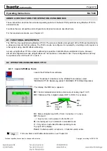
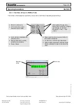
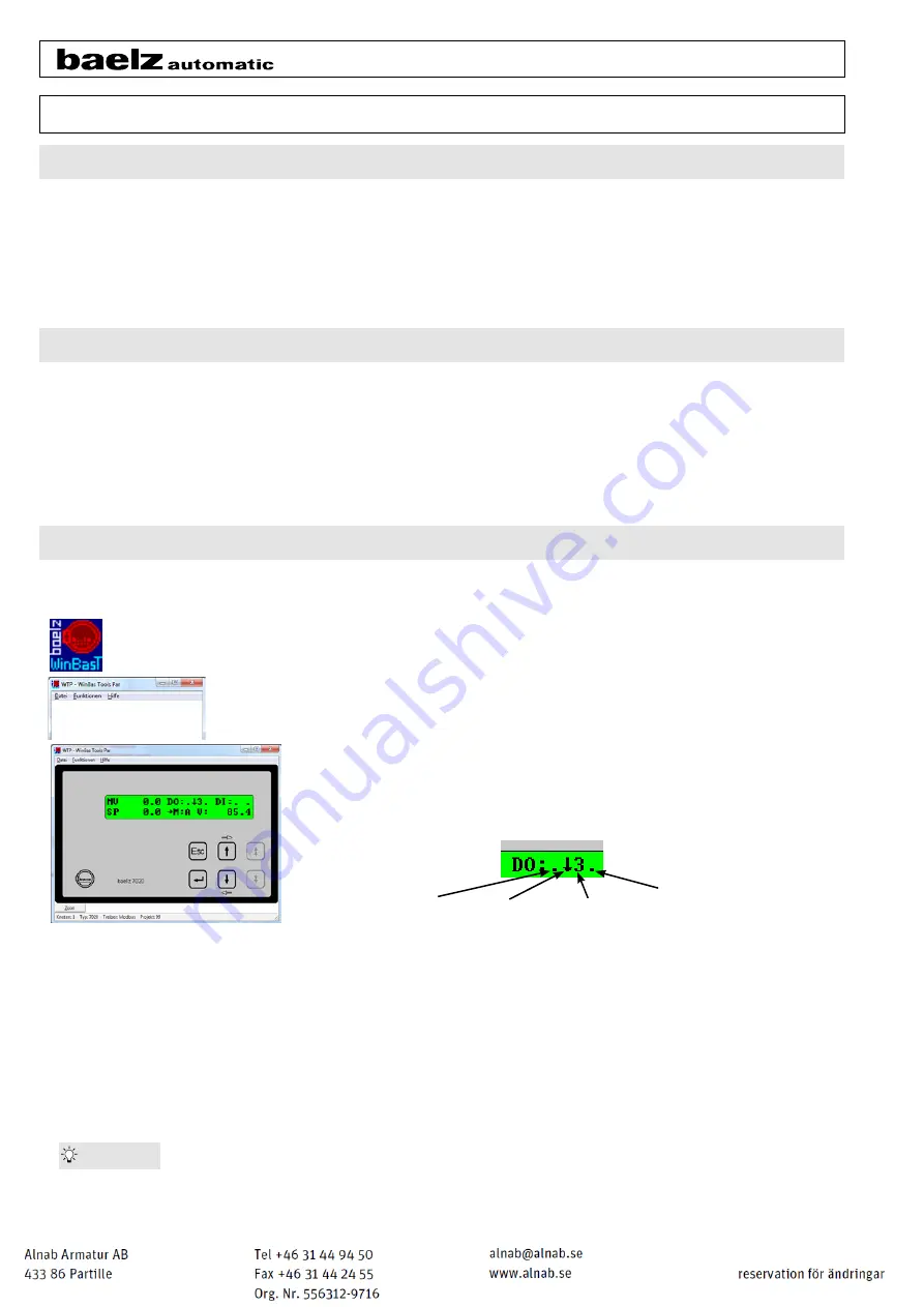
This display, the IMM menu, appears.
MV
= Actual manipulated variable, actual value at analog input 1 (AI1)
DO
= Statuses of the 4 digital outputs (DO1 to DO4). For example:
DI
= Status of digital input (DI1): Point = not active, 3 = active
SP
= Set point
→ = Input cursor, can be placed in front of M or V
M
= Generally set to A = Automatic in standard mode
V
= Only active in extended Modbus operating mode
Top right of the display:
Point
= Collective alarm not active, A = Collective alarm active
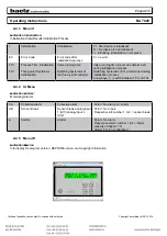
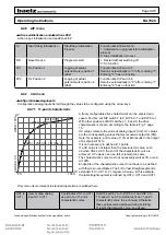
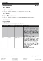
Tip:
For menu items and WinBas abbreviations, see Chapter A4
DO1:
not
active
DO2:
closed is
active
DO3:
active
DO4:
not
active


