Page 23/24
Operating Instructions
BA 7020
Technical specifications subject to change without notice
Copyright according to ISO 16016
BA_7020_00_EN_MJ_4917
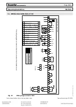
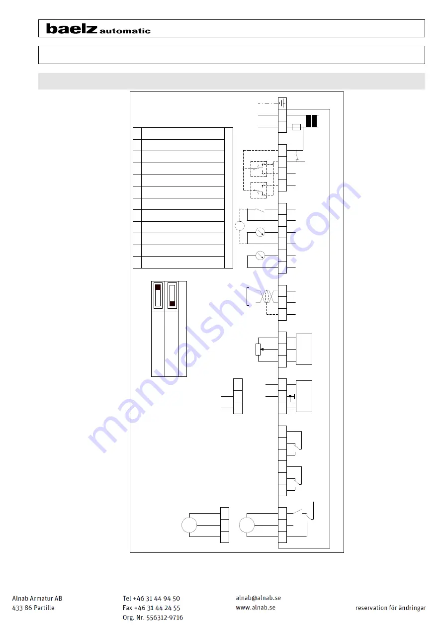
10. WIRING DIAGRAMS BAELZ 7020
c
m
o
I
91
6
7
8
9
12
DO4 Switch-point set = 0
-
> 1
Split-range
Split-range
Split-range
Characteristic for actuator
Operating mode 0=DIP / 1=RS485
Initialization start=0
-
>1 stop=1
-
>0
DO3 Switch-point set = 0
-
> 1
AI2 0 = U / 1 = I
DI
P-S
wi
tch
es
1
A
B
RS
48
5
1
2
3
4
5
6
7
8
9
1
Te
l.
07
13
1/
15
00
-
0
Fa
x.
07
13
1/
15
00
21
K
oe
pf
fs
traß
e
5.
D-
7407
6
H
eil
br
on
n
S
o
h
n
VD:
A
4
_
E
L-
AS
Z
e
ic
hnung:
U
rs
pr
ung:
AS
B_
702
0_
V1.
3.
sk
f
Ä
n
d
e
ru
n
g
Ge
p
r.
B
ea
rb.
D
at
um
TS
0
4.
0
7.
17
W
.B
ä
lz
&
A
n
sc
hl
u
ss
bi
ld
b
ael
z
7020
Co.
&
G
m
b
H
2
3
26
38
Digi
tal
P
os
ition
er
ba
el
z 7
02
0
GND
A
R=
5k
Oh
m
PE
N
L
+
-
Bl
M
Rd
Ye
12
Lo/DO1
14
Lu/DO2
20
DI
22
24V
23
AO1 (U)
24
GND
25
AO2 (I)
93
92
AI
1
Lin
Lout
S1
5
4
97
98
99
Bl
Bn
Rd
AI
2
U
0
I
0/
2.
..10V
+
-
0/
4.
..20m
A
U
0
-
+
39
40
B
GND
Ty1
8
Rd
M
Bl
Ye
97
98
99
Ty 6
u.
Ty
130
+
-
N
Li
n
2
AI2 0 = 0V/0mA 1 = 2V/4mA
3
AO1/2 0 = 0V/0mA 1 = 2V/4mA
4
Actuator-spindle 0=0V=Out/1=0V=In
5
10
11
F1
1,6
A
T
U
+
S =
S
af
ety
op
er
at
ion
N =
N
orm
al
op
er
at
ion
Cod
e
S1
E4
E5
E6
E1
E2
E3
DO3
DO4
D
O2
D
O
1
AS
B_
7020
_V
1.
3
F200
0245
0
213
m
m
98,
5
m
m
FP
O
T
Fig. 16:
Wiring diagram baelz 7020
This wiring diagram can also be found on the inside of the actuator cover
.


