12 |
36
W. Baelz & Sohn GmbH & Co.
· Koepffstrasse 5 · 74076 Heilbronn · Germany ·
www.baelz.de Seite | Page
Motorized Linear Actuator
baelz 373-E45
5. COMMISSIONING
Compare the thrust of the actuator and the set travel with the valve specifications. Overloading
can result in severe damage to the valve.
Pay attention to moving parts during fitting and adjustment. Risk of injury and substantial
material damage.
Actuators which are supplied fitted with a valve are set to the appropriate
valve stroke length. When an actuator with a 7020A digital positioner is
fitted to a valve, an initialization run must be carried out to set up the
actuator according to the valve type.
Attention
5.1 Limit switch settings
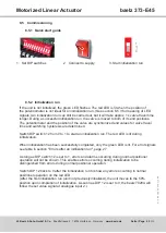
By default, the actuator is switched off in the end positions by the "DE" switches (wiring
diagram, Fig. 9, page 21). These are factory-set to the force indicated on the nameplate.
5.2 Test run
5.2.1 Checking the direction of rotation
● Adjust the actuator manually to roughly the middle position.
● In direction of travel CLOSE, switch the actuator on and watch the direction of rotation.
● If the direction of rotation is wrong, switch off immediately.
● Check wiring (jumpers).
● Repeat the test run.
If the direction of travel is set incorrectly, damage to actuator and valve is
imminent as the limit switches will not function with the wrong direction of
rotation!
Attention
5.2.2 Switching off in end positions
Risk of electric shock!
Danger
If the switches in the actuator are not factory-wired, check proper switching off in end positions:
With the cover removed, the linear actuator may only be operated briefly for test runs or
when performing absolutely essential adjustments on electrical components, such as
potentiometer, limit switches or positioning electronics.
While performing this activity, there is unobstructed access to hazardous, live, exposed,
moving and rotating parts. Adjustments performed incorrectly or without exercising the
necessary caution may result in death, serious injury or substantial material damage.
Any operation of the linear actuator with the cover removed for a purpose other than
that described above is prohibited.
Use an insulated screwdriver to actuate the switching rollers of the DE switches as shown in
the wiring diagram, Fig. 9, page 21, and check that the each switch actually switches off the
motor. If necessary, change the motor supply jumpers.
Summary of Contents for BA 373-E45
Page 36: ......


