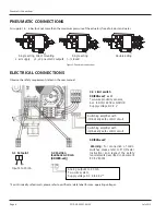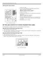
PNEUMATIC CONNECTIONS
Air supply: 1 4…6 bar (but not more than the maximum pressure of the actuator), free of oil, dust and water
Single acting, direct mounting
Single acting
Double acting
s air supply y1, y2 pneumatic outputs (--) closed
Figure 5: Pneumatic connections
ELECTRICAL CONNECTIONS
Observe the safety requirements listed in the user manual
3.3 Limit switch
SRI990-xxxT
or
U
Two-wire proximity sensors,
Acc. to DIN 19234 or NAMUR
Supply voltage DC 8 V
SRI990-xxxV
Warning
: For connection of micro
switches please refer to MI (Master
Instruction) and respect the safety
requirements described in document
EX EVE0001.
Switching amplifier with
intrinsically safe control circuit
Switching amplifier with
intrinsically safe control circuit
3.1 Setpoint
Input 4 to 20 mA
3.2 Position
feedback 4-20 mA
(SRI990-xxQ)
Analog output 4 to 20 mA,
Two-wire system,
Supply voltage DC 8 to 48 V*
* For intrinsically safe circuits, please refer to certificate / data label for max operating voltages
Pneumatic Connections
Page 8
July 2013
POS-QS-00007-EN-02
Summary of Contents for RCV SRI990
Page 1: ...Valve Positioners SRI990 Analog Positioner POS QS 00007 EN 02 May 2018 Quick Start Guide...
Page 2: ...Valve Positioners SRI990 Analog Positioner Page ii July 2013 POS QS 00007 EN 02...
Page 4: ...Valve Positioners SRI990 Analog Positioner Page iv July 2013 POS QS 00007 EN 02...
Page 11: ...INTENTIONAL BLANK PAGE Quick Start Guide Page 11 July 2013 POS QS 00007 EN 02...


