


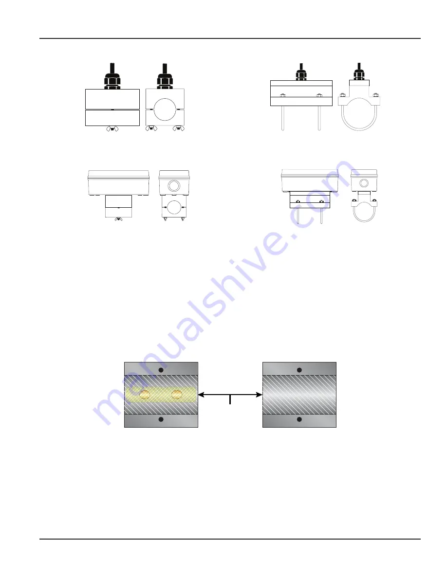
Remote System with Small Pipes
Side View
Top View
Figure 4: Pipes and tubing 1/2…2 in.
Side View
Top View
Figure 5: U-bolt connections, ANSI and copper 2 in.
Integral Systems with Small Pipes
Side View
Top View
Figure 6: Integral
Top View
Side View
Figure 7: Integral with u-bolt
INSTALLATION PROCEDURE
The small pipe transducers are fixed to pipe sizes between 1/2…2 in. Do not attempt to mount the transducers onto a pipe
that is either too large or too small for the transducer.
1. Clean the surface of the pipe. If the pipe has external corrosion or dirt, wire brush, sand or grind the mounting location
until it is smooth and clean. Paint and other coatings, if not flaked or bubbled, need not be removed. Plastic pipes typically
do not require surface preparation other than soap and water cleaning.
2. Apply a thin coating of acoustic coupling grease to the half of the housing where the transducer will contact the pipe.
See
Generally, a silicone-based grease is used as an acoustic couplant, but any good quality grease-like substance that is rated
to not flow at the operating temperature of the pipe is acceptable. For pipe surface temperature over 130° F (55° C), use
high-temperature paste (P.N. D002-2011-012) or non-silicone paste (P.N. D002-2011-009).
1/16 in. (1.5 mm)
Acoustic Couplant
Grease
Figure 8: Application of acoustic couplant
3. On horizontal pipes, mount the transducer in an orientation so the cable exits at ±45 degrees from the side of the pipe. Do
not mount with the cable exiting on either the top or bottom of the pipe. See
. On vertical pipes, the
orientation does not matter.
4. Tighten the wing nuts or U-bolts enough to hold the transducers in place, but not so tight that all of the couplant
squeezes out of the gap between the transducer faces and the pipe or from the gap between the transducer halves.
5. Route the remote transducer cables back to the flow meter location, avoiding high voltage cable trays and conduits.
Installation Procedure
Page 3
March 2021
IND-UM-02649-EN-05


