


6
Programming the Model 340BN Transmitter
Prior to introducing the Model 340 BN onto a BACnet
®
network, it
must be configured for the type of input signal, pipe size, desired
units of measure, filter coefficient, and temperature sensor. The
default network address should be assigned to an unused ad-
dress to avoid conflicts with other instruments on the BACnet
network. To change settings in the 340BN transmitter, Windows
®
based Badger Meter software must be installed and new values
entered as outlined below:
1. Install the Badger Meter Combo PC Software.
2. Connect the PC to the Model 340BN transmitter using the
Badger Meter Model A301 communications cable. Plug the
Model RS232 connector on the Model A301 cable to the Model
340BN socket labeled “D.I.C. Comm port”, taking care to prop-
erly align the tab on the plug and socket to maintain polarity.
Plug the Model DB9 connector on the opposite end of the
Model A301 cable to an available PC communications port. If
a cable with a Model DB9 connector is not available, a USB to
DB9 adapter (e.g. IOGEAR GUC232A) can be used.
3. Connect the Model 340BN transmitter to a power supply.
4. Open the Badger Meter Combo PC Software.
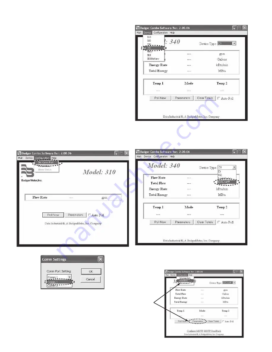
5. From the main screen, select Configuration and open the Set
Comm Port screen to assign the correct communications port
for the Model A301 cable as shown in the dialog boxes below.
Press the OK button to return to the Main screen.
6.
Select Device and 340 from the menu bar as shown below.
7.
Open the Device Type pull-down menu and select BACnet
protocol as shown below.
8. Select Configuration from the menu bar and open the Param-
eters screen as shown below.
To go to the
c
a
li
b
r
a
tion
s
etting
s
s
creen
s
elect
P
a
r
a
meter
s
from either
pl
a
ce
s
hown


