background image

2 - 11

Main parts

Main unit

Disassembly 

13 

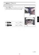
Tension base removal

1. Remove the screw 

1

, and then remove the cord clamp NK-4N from the

arm bed. 

2. Remove the 4 screws 

2

, and then remove the tension base assembly.

1

2

2

14 

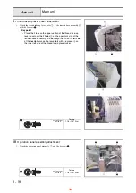
Needle plate removal

1. Remove the 2 screws 

1

, and then remove the needle plate 

1

.

1

1

8

Summary of Contents for EMP6

Page 1: ...EMP6 BMP8 Technical Training...

Page 2: ...ain unit Disassembly 1 Motor cover and carriage cover removal 1 Remove the screw cover 1 2 Remove the screw 1 and then remove the carriage cover 2 3 Remove the 2 screw 2 and then remove the motor cove...

Page 3: ...ver bottom assembly 1 2 Remove the 2 screws 2 and then remove the bed cover lid 2 from the bed cover bottom assembly 3 Remove the hinged door 3 and the spring 4 from the bed cover bottom assembly 4 Re...

Page 4: ...Remove the 2 screws 1 and then remove the arm cover R lid 2 Key point Remove the thumb bolt M4S from the operation panel assembly before removing arm cover R 3 Remove the 3 screws 2 and then remove t...

Page 5: ...Main unit Main parts 4 Arm cover L removal 1 Remove the 3 screw covers 1 2 Remove the screw inside the cover 1 and the 2 screws outside the cover 2 and then remove arm cover L 2 2 1 1 Inside Outside...

Page 6: ...al 1 Remove the 2 screw covers 1 2 Remove the 2 screws 1 and then remove the base cover R lid 2 3 Removes the 3 screws 2 and then remove the base cover R 3 Key point Fully draw the feed final assembly...

Page 7: ...move the 3 screws 2 and then remove the base cover L 3 Key point Fully draw the feed final assembly toward you before removing the base cover L 1 1 2 3 2 7 LED drive PCB removal 1 Disconnect the lead...

Page 8: ...and then remove the operation panel assembly 1 1 1 1 1 12 Thread take up cover removal 1 Remove the 2 screws 1 and then remove the thread take up cover 1 Key point The pin protruding from the needle b...

Page 9: ...base removal 1 Remove the screw 1 and then remove the cord clamp NK 4N from the arm bed 2 Remove the 4 screws 2 and then remove the tension base assembly 1 2 2 14 Needle plate removal 1 Remove the 2 s...

Page 10: ...nly for thread tension A A 1 6 2 3 4 5 4 S51 S51 S51 2 Tension base bracket removal 1 Remove the cord bush KR51 1 from the tension base bracket and then remove the tension base lead wire assembly 2 fr...

Page 11: ...sor PCB assembly and head PCB assembly removal 1 Disconnect the FFC SML2CD H from the head PCB assembly 1 6 locations 2 Remove the 4 screws 1 and then remove the head PCB assembly 3 Remove the 2 screw...

Page 12: ...ve the screw 3 and then remove the cutter cover assembly from the thread holder base assembly 6 locations 3 Remove the retaining ring CS5 from the cutter cover assembly and then remove the 6 NT lower...

Page 13: ...ews 1 and then remove the thread tension bracket base 2 Remove the 6 screws 2 and then remove the thread tension bracket base 3 Remove the 6 thread guide cover assemblies 2 from the thread take up lev...

Page 14: ...e the 4 screws 1 and the 4 plain washers M8 and then remove the arm bed from the base frame 1 1 2 Idle pulley assembly removal 1 Remove the 4 screws 1 and then remove the 2 bushing pressers 2 Remove t...

Page 15: ...Disconnect all connectors from the main PCB 2 Remove the 4 screws 1 and then remove the main PCB assembly 1 3 Remove the 4 screws 2 and then remove board holder U 2 and board holder D 3 1 2 2 3 1 2 1...

Page 16: ...2 55 Disassembly Power unit Main unit 15...

Page 17: ...assembly 1 from the power PCB assembly 100 or 200 2 Remove the 4 screws 1 and then remove the power unit cover assembly from the power unit stay 3 Remove the 4 screws 2 and then remove the insulation...

Page 18: ...2 73 Disassembly Operation panel Main unit 17...

Page 19: ...o the needle bar case final assembly with the 4 screws 1 2 Attach the cord clamp NK 4N to the tension base cord at a point 125 mm from the tension base and secure it to the arm bed with the screw 2 1...

Page 20: ...the 2 holes 3 on the operator s side of the tension base assembly and then align the pin on the left side of the needle bar case final assembly with the groove 4 on the inner left side of the thread...

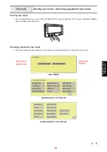
Page 21: ...witch on with the START STOP button THREAD CUT button THREAD GUIDE button simultaneously held down Selecting adjustment test mode 1 Select the desired adjustment mode by pressing the corresponding mod...

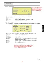
Page 22: ...screen shown below appears MAIN MOTOR TEST Opens the main shaft motor test mode screen XY MOTOR TEST Opens the X Y carriage motor test mode screen TRIM MOTOR TEST Opens the trim thread cut motor test...

Page 23: ...e center of S hoop Changes the X and Y carriage origins 10 10 SAVE Saves changes to the X and Y carriage origins in the EEPROM SPEED Sets the motor speed 100 1200 PITCH Sets the pitch 0 0 20 0 REPEAT...

Page 24: ...r WIPER ON OFF Turns the wiper on and off MOVE JUMP Moves the jump bracket JUMP ON OFF Turns the jump bracket on and off CLOSE Closes the WIPER JUMP MOTOR TEST screen 8 PICKER MOTOR TEST MOVE PICKER M...

Page 25: ...line is displayed until the status of the NEEDLE UP sensor changes after power has been turned on INITIALIZE Moves the angle of the main shaft to the initial adjustment position approx 350 deg CLOSE C...

Page 26: ...ustment and left right adjustment are displayed and the read needle bar data is displayed to the right of these 13 characters FRONT BACK POSITION Moves the needle bar to the position for front back ad...

Page 27: ...djustment are displayed and the read needle bar data is displayed to the right of these 13 characters FRONT BACK POSITION Moves the needle bar to the position for front back adjustment RIGHT LEFT POSI...

Page 28: ...splayed Menu descriptions 1 Switch test Select this mode to check whether the three push buttons are operating correctly The button on the screen turns red while the actual button is held down 2 LED t...

Page 29: ...age of Setting Menu 4 LCD Contrast Select this mode to adjust the contrast on the LCD screen 5 Emb Card Select this mode to check whether the embroidery card slot is operating correctly Insert an embr...

Page 30: ...ess Adjustment screen Touch the center of the symbols with a stylus pen in the following order top left corner bottom left corner bottom right corner top right corner and center When the touch panel i...

Page 31: ...rip button resets Trip Stitches and Trip Time to zero Parameters Default Thread spool All color information set for spools is cleared resulting in no spool set Reserved thread All spools are released...

Page 32: ...a needle bar number 1 Start up Test mode 2 Select MAIN BOARD TEST MODE 3 Select CASE MOTOR TEST 4 Select a needle bar number used for an adjustment by pressing or key NEEDLE BAR DATA ON BAR CODE Prod...

Page 33: ...ent front back 4 20 2 Needle position adjustment right left 4 21 3 Needle bar rising length and needle space adjustment 4 22 4 Needle bar height adjustment 4 23 5 Rotary hook stopper adjustment 4 24 6...

Page 34: ...screw 1 at the lower section of the needle bar case final assembly 5 Move the case positioning plate assembly back and forth to adjust the needle front back position 6 Tighten the screw 1 7 Check the...

Page 35: ...dle bar until the needle tip enters the needle hole 4 Loosen the 2 screws 1 5 Move the change box right and left to adjust the needle right left position 6 Tighten the 2 screws 1 7 Check the position...

Page 36: ...length and the needle space and tighten the 3 screws 1 5 Check the needle bar rising length and the needle space for the other 5 needle bars Key point Pressing and selects the other needle bars 1 Torq...

Page 37: ...bar height for the other 5 needle bars Key point Pressing and selects the other needle bars Clearance between top edge of rotating hook s tip and top edge of needle hole 1 8 2 2 mm Alignment of needl...

Page 38: ...he clearance between the rotary hook stopper and the rotary hook 3 Tighten the screws 1 and 2 Clearance between rotary hook stopper end face and rotary hook 0 65 0 95 mm 1 Torque 0 59 0 78 N m 2 Torqu...

Page 39: ...ars Clearance between section surrounding eye of needle and bottom face of presser foot 0 5 1 1 mm 1 Torque 0 78 1 18 N m Screw 0 5 1 1 mm The clearance between the section surrounding the eye of the...

Page 40: ...tical set assembly surely 4 Loosen the screw 1 5 Push the top dead center plate towards the needle bar downward so that the cushion rubber is compressed slightly approx 0 3 mm and tighten the screw 1...

Page 41: ...ight of the needle hole s top edge Raise the rack to its original position 4 Repeat the same steps to check the height for the other needle bars numbers 2 to 6 Key point Pressing and selects the other...

Page 42: ...ves 3 Loosen the screw 1 4 Manually lower the needle thread assembly s rack to the bottom and move the hook to the position immediately before the needle hole 5 Manually hold the bush and rotate the h...

Page 43: ...Press MOVE ORIGIN POSITION to move the hook to its origin 3 Press MOVE THREAD SET MOTOR to check that the hook passes through the needle hole 4 Check that the hook passes through the needle hole for...

Page 44: ......
Page 45: ...1 05 mm between the bobbin and the picker tip 6 If the clearance cannot be adjusted by following the above procedure move the picker holder attachment screw 1 back and forth to adjust the clearance Cl...

Page 46: ...and then TRIM MOTOR TEST 2 Press MOVE ORIGIN POSITION to move the needle plate base assembly s movable knife to its origin 3 Loosen the 2 screws 1 4 Adjust the position the movable knife stops 5 Tight...

Page 47: ...ment load of the movable and fixed knives 2 When the engagement load is not within the specifications insert a spacer below the collar of the movable knife as shown in Figure 2 3 Measure the engagemen...

Page 48: ...e thread presser base 3 Tighten the 4 screws 1 Clearance between wiper hook top face and thread presser cover 0 0 2 mm 1 Torque 1 18 1 57 N m Screw Bind M4X6 clearance 0 0 2mm 1 Wiper hook Thread pres...

Page 49: ...MAIN BOARD TEST MODE and then A D TEST 3 After the hoop stay assembly s LL hoop has been attached press LL to save the A D value 4 Replace the LL hoop with the S hoop and then press S to save the A D...

Page 50: ...test mode and only the A D test mode no other test modes will be accessible to the consumer Attach the hoop frame assembly to the machine Enter the test mode by pressing both the START STOP button an...

Page 51: ...ghten the 2 screws 2 5 Repeat the same steps to adjust the Y belt tension on the right side 6 Tighten the 2 screws 1 Load when the center of the Y belt is deflected 4 3 mm 2 35 2 55 N 240 260g 1 Torqu...

Page 52: ...2 Move the tension pulley plate assembly right and left to adjust the X belt tension 3 Tighten the 2 screws 1 Load when the center of the X belt is deflected 5 7 mm 1 27 1 47 N 130 150g 1 Torque 1 18...

Page 53: ...ve the motor holder up and down to adjust the motor belt tension 3 Tighten the 2 screws 1 Motor belt deflection when a load of approx 0 98 N 100 g is applied to the center of the motor belt 1 5 3 5 mm...

Page 54: ...1 2 Move the tension pulley right and left to adjust the timing belt tension 3 Tighten the screw 1 Timing belt deflection when a load of approx 1 96 N 200 g is applied to the center of the timing bel...

Page 55: ...52 WKUHH GURSV 2 52 RQH GURS 02 27 0 63 56 21 RQH GURS 02 27 0 63 56 21 RQH GURS 02 27 0 FP 02 27 0 63 56 21 RQH GURS 02 27 0 FP 02 27 0 FP 2 5 RQH GURS 2 5 WKUHH GURSV 2 5 RQH GURS 02 27 0 FP 02 27...

Page 56: ...OHU YHU KRXUV 1DPH RI JUHDVH RLO 4XDQWLW 2 5 RQH GURS 2 5 WKUHH GURSV 2 5 RQH GURS 1HHGOH EDU FDVH 0DLQWHQDQFH QHHGV WR EH FDUULHGRXW RQ D PDFKLQH DW KRXUV XVH LI WKH PDFKLQH LV XVHG IRU LQGXVWULDO SX...

Page 57: ...QJ EUXVK WR UHPRYH DQ OLQW DQG GXVW IURP NQLYHV DQG URWDU KRRN 0DLQWHQDQFH 0DLQWHQDQFH 0DLQWHQDQFH 5HPRYH DQ OLQW DQG GXVW EHWZHHQ WHQVLRQ DGMXVWLQJ VSULQJ DQG EREELQ FDVH ZKHQHYHU RQH SUHZRXQG EREELQ...

Page 58: ...O 4XDQWLW 2 52 RQH GURS KHFN WKUXVW SOD RI ORZHU VKDIW 2 5 RQH GURS 5HPRYH GXVW DURXQG URWDU KRRN DQG EXVKLQJ 2 52 RQH GURS 2 52 RQH GURS 7KHUH VKRXOG EH QR GXVW EHWZHHQ ORZHU 02 27 0 FP VKDIW DQG EXV...

Page 59: ...19 XY moving error 5 12 EEPROM read write error 3 98 EEPROM read error 3 5 Main motor rotate error 5 12 Main motor lock 5 12 Main motor encoder signal error 5 25 Main motor encoder connect error 5 25...

Page 60: ...et N Y Is the power cord properly connected to both the inlet and the plug outlet Connect it properly Is connector CN21 on the main PCB properly connected N Y Is lead on the panel properly connected t...

Page 61: ...Attach the groove cover C 5 to the rear of the base cover L lid 4 3 Attach the base cover L with the 3 screws 1 Key point Fully draw the X guide toward you before attachment 4 Attach the base cover L...

Page 62: ...1 2 Attach the groove cover C 5 to the rear of the base cover R lid 4 3 Attach the base cover R with the 3 screws 1 Key point Fully draw the X guide toward you before attachment 4 Attach the base cov...

Page 63: ...ide Inside 2 1 Screw Pan S P washer M4X10DB Taptite Cup B M4X14 18 Arm cover R attachment 1 Attach the arm cover R 1 with the 3 screws 1 2 Attach the arm cover R lid 2 with the 2 screws 2 Key point Re...

Page 64: ...Attach the spring 4 and the hinged door 5 to the bed cover bottom 3 3 Attach the bed cover lid 7 to the bed cover bottom assembly 6 with the 2 screws 2 4 Attach the bed cover bottom assembly to the ar...

Page 65: ...er attachment 1 Attach the motor cover 1 with the 2 screws 1 2 Attach the carriage cover 2 to the X guide with the screw 2 3 Attach the screw cover 1 Torque 0 78 1 18 N m 2 Torque 0 78 1 18 N m 2 1 2...

Reviews: