WARNING
Before installing your new amplifier, make sure the fuse is properly installed.
Never change the value of the fuses. Use the fuses with the current and rated voltage in this
manual. Otherwise, it may cause a short circuit, smoke or even an explosion.
Do not install this unit in a location that would interfere with operation of the vehicle or may
cause injury to a passenger as a result of breaking.
To ensure proper operation of this unit while maintaining good thermal dissipation, be sure to
leave enough space above the amplifier for proper ventilation. Do not cover the amplifier with a
carpet or blanket.
Connect the cable (+) battery to the positive terminal of the amplifier (B +) and ground wire
(GND) of the amplifier to the vehicle chassis.
This unit is for installation of 12V and negative grounding. Before performing an installation in a
van, truck or bus, check the battery voltage.
The black wire is the ground wire.
When installing this unit, always connect the ground wire first. Check the ground wire is properly
connected to the vehicle chassis.
If by some factor, the cable connected to the vehicle, is loosen or falls could result in fire, smoke
or failure.
The amplifier must be installed on a flat surface. Installing it on a surface that is flat or bumpy,
may cause defective operation.
Do not let this unit, contact with liquids that could lead to electric shock, smoke or overheating.
If by any problem with the instalation of this amplifier, the fuse blows. Disconnect the cables and
check all connections (power and speakers). Once you determine and solve the problem, replace
the fuse / s for a new nominal current and voltage identical.
If none of these works, contact your nearest dealer.
BEFORE INSTALLATION
3
Summary of Contents for ELP 36.4
Page 6: ...ELECTRICAL DIAGRAM a Configuration Diagram for 4 Channel Stereo 6...
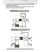
Page 7: ...ELECTRICAL DIAGRAM a Mode Setup diagram Bridge Bridge 7...
Page 10: ...www b52audio com NOTES...
Page 16: ...DIAGRAMA ELECTRICO a Diagrama de Configuraci n para 4 Canales Est reo 16...
Page 17: ...DIAGRAMA ELECTRICO b Diagrama de Configuraci n en Modo Puente Bridge 17...
Page 20: ...www b52audio com NOTAS...
Page 26: ...DIAGRAMA ELETRICO a Diagrama de Configura o para 4 Canais Est reo 26...
Page 27: ...DIAGRAMA ELETRICO b Diagrama de Configura o no Modo Ponte Bridge 27...
Page 30: ...www b52audio com NOTAS...
Page 31: ...MOBILE ENT E RTA INM E NT SY ST E M www b52audio com...


